Content last revised on October 2, 2026
Preventing Spurious Faults: Mechanical Mounting Torque Sequence and Thermal Guidelines for MCD162-14IO1
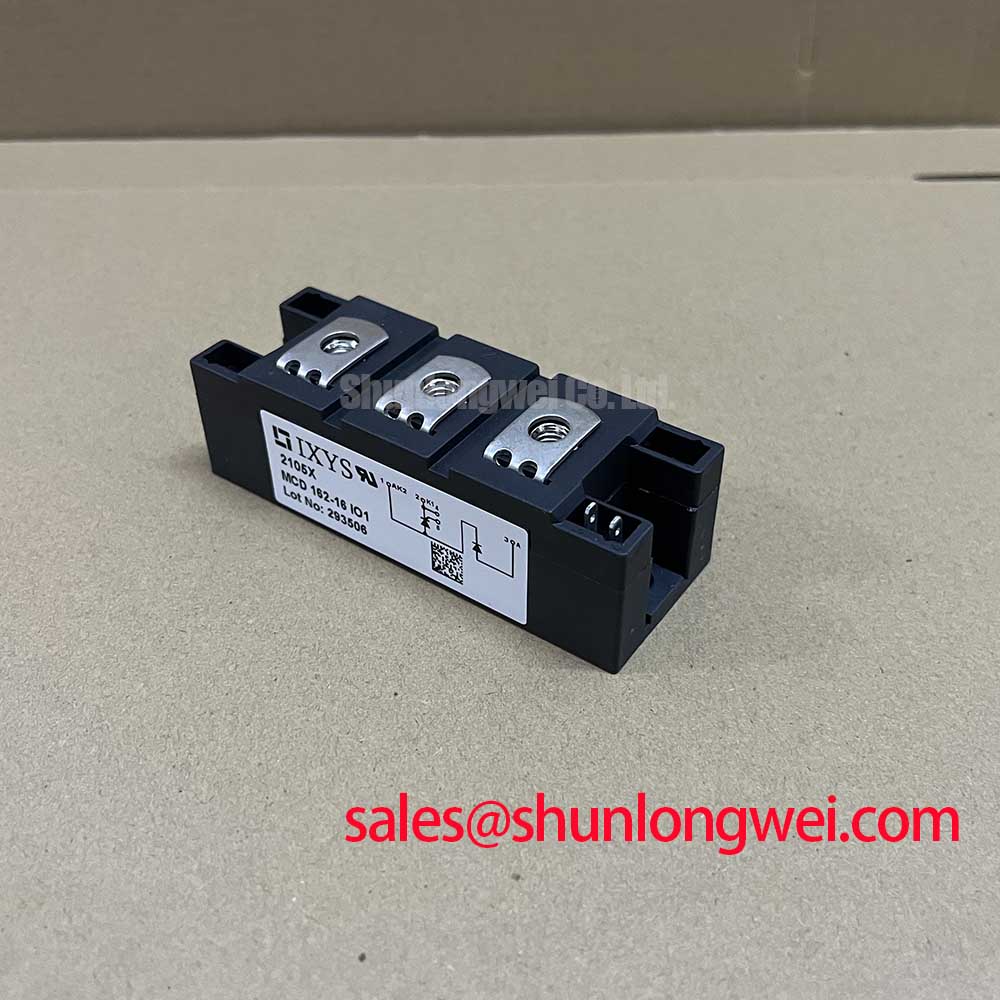
Begin incoming inspection by confirming the marking MCD162-14IO1, checking the module body and baseplate for visible damage, and comparing the nameplate ratings with the approved equipment documentation. The supplied official product data identifies this IXYS device as a 1400.0 V, 162 A module in a TO-240AA package. These are the primary identity and electrical boundary values available for this product page; they should not be expanded into unverified thermal, surge, or switching ratings.
For a high-voltage three-phase motor solid-state soft starter, the copper baseplate must sit evenly against the prepared heatsink surface. A Design Consideration is to inspect both surfaces for burrs, contamination, uneven machining, or trapped particles before applying the approved thermal interface material. The purpose is to establish consistent contact pressure across the baseplate without bending the module or concentrating force near one mounting point. The exact thermal resistance, allowable case temperature, and thermal interface requirements must be verified from the applicable IXYS datasheet or assembly drawing before the thermal design is released.
The mechanical sequence should be controlled by the system assembler rather than assumed from the package name. Install the module against the heatsink, start all specified fasteners by hand, and bring them into contact using a gradual alternating sequence. The final torque value, fastener type, washer arrangement, and any required tightening stages are not included in the supplied product parameters, so the original manufacturer documentation should control those values. After tightening, confirm that the baseplate has not shifted and that the power terminals remain aligned with the busbar or cable layout.
💡 Bench Tip: Keep the module disconnected from every energized circuit, use ESD precautions, and record a cold-state comparison of terminal resistance against a known-good reference before applying any high voltage.
A resistance check is useful for identifying an open connection, an unexpected short, or a wiring error, but a multimeter reading is not a substitute for the module’s rated blocking-voltage test. The meter’s diode mode may show a junction-related response depending on the internal thyristor path and test polarity, yet the reading should not be assigned a universal pass or fail voltage without the manufacturer’s test conditions. Measure each accessible power path in both polarities, document the result, and compare identical positions within the three-phase assembly.
Fuse coordination also requires source documentation. The appropriate fuse type, clearing characteristic, and I²t relationship depend on the soft-starter topology, prospective fault current, wiring impedance, and the thyristor module’s published surge data. Since the supplied official parameter set does not include an I²t value or fuse coordination table, the protection selection must be verified against the applicable IXYS technical documentation rather than inferred from the 162 A rating.
Assembly Integrity and Layout Architecture: Reverse Recovery Charge Temperature Coefficient Considerations for MCD162-14IO1
When this dual thyristor module is evaluated for a three-phase motor soft starter, the layout review should begin at the commutation path. Keep the high-current conductors short and mechanically supported, provide balanced phase routing, and prevent control wiring from running parallel to high di/dt power conductors wherever the enclosure allows. These are Design Considerations for reducing unwanted coupling; they do not represent an MCD162-14IO1 datasheet guarantee.
The supplied official data confirms the voltage and current class, but it does not provide reverse-recovery charge, reverse-recovery time, peak reverse-recovery current, junction-temperature coefficients, or a soft-recovery classification. Those values must be obtained from the correct IXYS electrical characteristics and test conditions before a switching-loss or EMI model is created. A thyristor module used in line-frequency phase control should not be assigned diode recovery behavior from a different device family.
For background on fast-recovery diode behavior, engineers may consult ROHM High-Speed Fast Recovery Diodes. That reference is useful for general semiconductor terminology, but it should not be treated as a specification for the IXYS MCD162-14IO1. The actual commutation behavior of this module must be established from its own manufacturer data and the intended circuit operating point.
During bench evaluation, place voltage probes and current probes at positions that represent the actual semiconductor terminals rather than distant points on the cabinet bus. Observe the line voltage, load current, gate trigger timing, and any transient appearing across the device during turn-on and commutation. If the measured waveform contains unexpected ringing, the investigation should include probe-ground inductance, busbar geometry, snubber condition, phase imbalance, and trigger wiring. A single waveform symptom should not be assigned to one component without checking the complete signal path.
Snubber selection, dv/dt immunity, critical rate-of-rise behavior, and surge-current capability require the product’s published limits. They should be reviewed alongside the motor’s starting profile and the soft-starter bypass arrangement. The 1400.0 V rating is an official voltage value, not permission to operate at that voltage continuously under every temperature, transient, or insulation condition. System designers should verify peak voltage margins during controlled switching tests and confirm that the enclosure insulation system meets the required equipment standard.
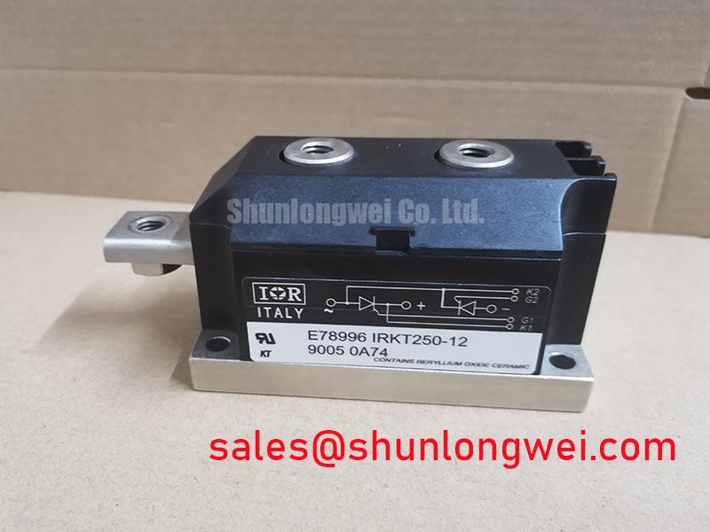
For a broader explanation of power semiconductor operating principles and switching stress, the engineering team can use The Ultimate IGBT Knowledge Base as a general technical reference. Its subject scope is broader than this dual thyristor module, so model-specific limits must remain tied to IXYS documentation. A neutral comparison reference such as TT570N16 may assist a sourcing review, but electrical, mechanical, and gate-drive compatibility must be checked independently rather than assumed from similar current or voltage markings.
Benchtop Waveform Tuning: Gate Trigger Current Dynamics for MCD162-14IO1
Before connecting a trigger circuit, identify the gate and cathode terminals from the official IXYS pinout or mechanical drawing. Do not infer terminal polarity from the position of a neighboring module or from a visually similar TO-240AA device. With the power path isolated, use continuity and resistance checks to confirm that the trigger wiring reaches the intended semiconductor position, then inspect the trigger pulse with an oscilloscope using an isolation method suitable for the circuit voltage.
The supplied product information does not include a gate trigger current, gate trigger voltage, latching current, holding current, minimum gate pulse width, pulse rise-time requirement, or recommended gate-drive circuit. Consequently, values such as a gate current above a particular threshold, a specified pulse rise rate, or a back-porch current must not be presented as official MCD162-14IO1 limits. Obtain these parameters from the manufacturer’s gate characteristics and apply the test conditions stated there.
A Design Consideration for bench tuning is to confirm that the trigger pulse remains present at the module terminals after cable resistance, connector resistance, isolation components, and any series protection network are included. The oscilloscope should capture the trigger signal and the corresponding anode-to-cathode response on the same time base. If one phase fires later than another, inspect the pulse transformer or optocoupler channel, gate return routing, connector seating, control reference integrity, and phase synchronization before changing the firing algorithm.
Multi-pulse triggering may be considered when the control architecture and the manufacturer’s gate requirements support it, but the timing pattern must be validated against the motor soft-starter controller. Repeated pulses can increase control-side dissipation and may interact with isolation or pulse-shaping components. The system engineer should determine the pulse schedule from the verified gate data, required firing-angle resolution, line frequency, and noise environment.
Localized heating cannot be diagnosed from trigger timing alone. Review heatsink contact, phase current balance, thermal sensor placement, fuse condition, motor inrush behavior, and the thyristor’s on-state voltage under the actual load. If the module is removed for testing, allow the assembly to return to a defined cold condition before comparing measurements. The 162 A official rating identifies the device’s stated current class, but it does not replace a system-level current, temperature, duty-cycle, or overload assessment.
For procurement and repair teams, the most useful incoming record includes the module marking, package condition, terminal mapping, cold resistance observations, control-channel identification, and the exact equipment position from which the device was removed. This information supports controlled replacement evaluation without assuming that a visually similar dual thyristor module has matching gate or thermal characteristics.
MCD162-14IO1 Operational Boundaries: Evaluating Dynamic Firing-Angle Adjustment Limits
In a three-phase motor solid-state soft starter, firing-angle adjustment changes the time at which each thyristor pair begins conducting during the line cycle. The resulting motor voltage, current, torque, power factor, harmonics, and reactive demand are determined by the supply waveform, motor impedance, load inertia, control synchronization, and bypass strategy. The MCD162-14IO1 product data supplied here confirms 1400.0 V, 162 A, and TO-240AA, but it does not define a guaranteed firing-angle range or a universal motor-start profile.
An Engineering Recommendation is to evaluate the control range gradually on a protected test setup, beginning with low stored energy and a verified phase sequence. Record line-to-line voltage, phase current, trigger timing, motor acceleration, heatsink temperature, and any abnormal acoustic or electrical behavior. The controller should inhibit firing if synchronization is lost, if a phase is missing, or if the measured current exceeds the independently established equipment limit.
A nominal control angle should not be converted directly into a guaranteed motor voltage or torque value without modeling the actual load. A lightly loaded motor, a high-inertia machine, and a motor connected to a transformer or long cable can respond differently to the same trigger command. Designers should therefore use the motor manufacturer’s starting requirements and validate the complete soft-starter assembly under representative load conditions.
Power factor and reactive power should be measured at the supply terminals rather than inferred from the firing command alone. The measurement should include the instrument’s bandwidth, phase accuracy, crest-factor capability, and the presence of bypass contactors or input reactors. If the system uses an external bypass after acceleration, compare the pre-bypass and post-bypass readings so that semiconductor conduction effects are not confused with motor or supply behavior.
The module’s voltage rating also requires system-level review. Confirm the actual line-to-line and transient environment, insulation coordination, protective devices, grounding method, and clearance and creepage design. No independent EMC or safety certification should be attributed to the semiconductor module itself; compliance belongs to the completed equipment evaluated under its applicable standards.
For replacement work, verify the original connection diagram, gate-drive interface, heatsink arrangement, fuse coordination, and controller timing before installation. The neutral product reference TT570N16 can be reviewed as a separate device listing, but substitution decisions remain system-dependent and require confirmation of all electrical and mechanical conditions.