





Content last revised on October 2, 2026
Assembly Integrity and Surge Protection for MCD250-16IO1
Trace each power terminal and gate lead against the equipment schematic, then check cold-state polarity and isolation between the accessible terminals before fitting MCD250-16IO1. Record the meter range, lead orientation and readings for comparison with an approved reference unit. A diode-mode result alone cannot establish a thyristor’s blocking-voltage capability: the meter applies a low-energy test that does not reproduce service conditions.
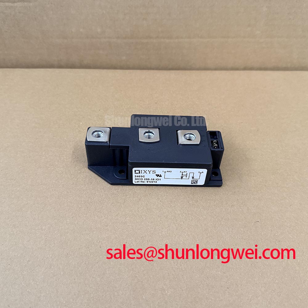
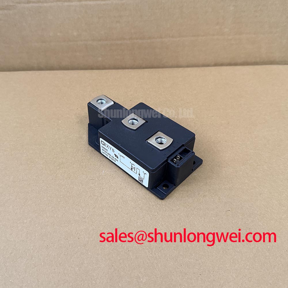
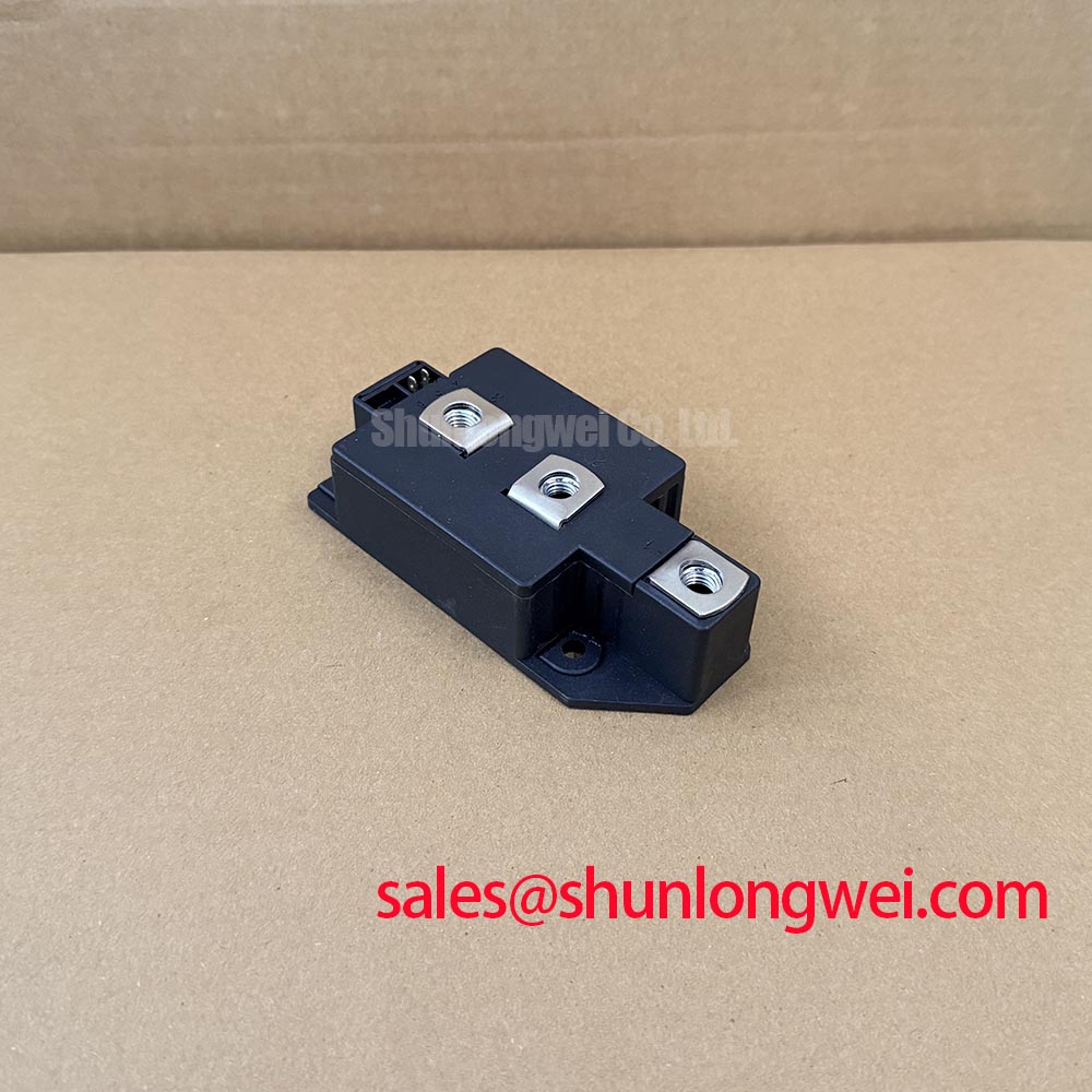
Inspect the TO-240AA mounting interface, terminal alignment and mating busbars for uneven contact. IXYS identifies this part as a dual thyristor module in a TO-240AA package (Official Specification). The supplied product data does not establish a mounting torque, terminal assignment or voltage rating, so use the applicable module drawing and equipment procedure for those checks rather than transferring values from a similar-looking assembly.
For AC-input surge protection, compare the equipment’s documented surge exposure with the installed metal oxide varistor, fuse and clamping arrangement. As a Design Consideration, place protective elements so the measured terminal transient remains within the applicable thyristor limits during system testing. Coordinate the fuse’s clearing characteristic and let-through energy with the module’s published surge-current and I²t limits when those specifications are available; package size is not a substitute for that comparison.
RC Snubber Layout and Trigger Control
Capture the voltage across each thyristor during commutation and inspect any unintended gate activity at the same time. A sharp off-state voltage transition can contribute to unwanted turn-on, but a similar waveform can also reflect probe placement or another switching branch. Repeat the measurement with a consistent probe connection and compare it with a known-good path.
As a Design Consideration, keep the snubber connection close to the terminals it protects to limit loop inductance. Select the resistor, capacitor and any series reactor from measured off-state transients, switching duty, component dissipation and the thyristor limits in the applicable datasheet. Final values belong to the system design and switching tests, not to the TO-240AA package designation. Inspect installed resistors and capacitors for changed values or damaged connections before changing the circuit.
Compare gate pulses at the driver output and at the module terminals under the same operating condition. Trigger-current and trigger-voltage limits, where documented, matter when assessing a weak or mistimed pulse; neither can be inferred from a static meter check. For phase-controlled equipment, log firing angle alongside the measured current waveform. A control change may alter harmonic content and commutation conditions, so verify the result at system level. For a neutral comparison of another IXYS dual-thyristor listing, review MCD312-16IO1 against the required electrical ratings, terminals and mounting drawing rather than assuming interchangeability.
Mounting Contact and Thermal Assessment
Check the mating surfaces for debris and uneven paste transfer, then measure temperature at repeatable locations during a controlled load test. An irregular thermal pattern may indicate poor contact, uneven loading or another heat-path problem; temperature alone does not identify which one. Record ambient conditions and operating current so later measurements are comparable.
Do not assume a copper baseplate, a double-sided cooling arrangement or a specified junction-to-case thermal resistance from the package code. These details require the applicable module documentation. As a Design Consideration, apply the equipment’s approved interface material and fastening sequence, then check seating without distorting the assembly. Check estimated junction temperature under the measured duty cycle against the module’s documented thermal limits; do not treat heatsink temperature as junction temperature.
💡 Bench Tip: Discharge and verify isolation of the power circuit before touching gate leads or moving meter probes.
Field Diagnostics During Thyristor Commutation
Compare the current fall and reapplied voltage of each thyristor position during commissioning, using probe locations and operating conditions that can be repeated. Unexpected turn-on or a prolonged commutation interval calls for checks of gate timing, load current and the snubber path before a module fault is assigned.
MCD250-16IO1 is identified as a dual thyristor module, not a diode module or IGBT (Official Specification). Diode reverse-recovery figures and IGBT desaturation or short-circuit safe-operating-area procedures should therefore not be presented as its factory specifications. Assess thyristor turn-off behavior using the relevant commutation and off-state limits in the applicable documentation. IEC 60747-6, Semiconductor Devices — Thyristors provides the device-standard context; it does not certify a particular installation.
For a grid-tied static var compensator or thyristor-switched capacitor assembly, treat this module as a candidate for compatibility evaluation, not an approved replacement on the basis of topology alone. Match the circuit’s blocking requirements, current duty, gate drive, terminals and cooling arrangement to verified module specifications. If switching behavior needs wider circuit context, the discussion of Resonant Topologies in Home Appliances can inform waveform interpretation without establishing compatibility with that grid application.