








Content last revised on October 3, 2026
Baseplate Thermal Contact and Electrical Limits of the MCD312-16IO1
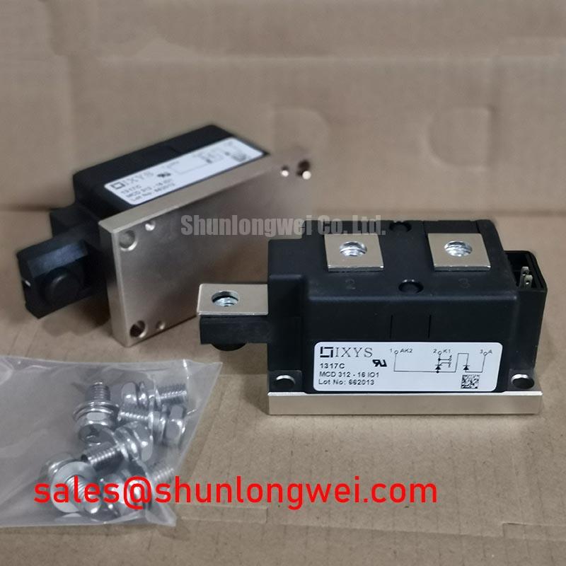
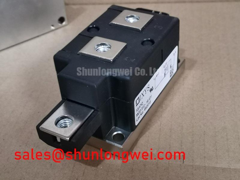
For a repair, inspect the heatsink seating area before fitting the module. Remove old interface material without damaging the mounting surface, then check that the new module sits evenly and that its terminals can be connected without mechanical strain. Uneven contact can raise junction temperature even when the circuit current remains within its nominal rating. As a Design Consideration, apply thermal interface material evenly and verify contact using the assembly procedure specified for the equipment.
The supplied product data confirms 1600 V, 312 A and TO-240AA, but does not establish a junction-to-case thermal resistance, mounting torque or fuse coordination value. Obtain those figures from the applicable IXYS datasheet and equipment service documentation before setting a thermal limit or tightening fasteners. A fuse’s current rating alone is not enough to establish semiconductor protection; its clearing characteristics must be checked against the module’s documented surge and I²t limits under the intended fault conditions.
When evaluating an MCD312-16IO1 for a medium-frequency induction melting or hardening furnace supply, compare the equipment’s measured load cycle, cooling arrangement and protective-device coordination with the documented module limits. This is a compatibility check, not an assertion that the module was specified for every furnace of that type.
Commutation Turn-Off Voltage and Recovery Checks
Trace the commutation path on the equipment schematic before attributing a voltage spike to the thyristor module. The MCD312-16IO1 is a dual thyristor module; a separate freewheel or recovery diode, if present in the system, must be identified from the actual circuit. Diode reverse-recovery peak current, recovery time and softness are diode-specific characteristics and should not be presented as MCD312-16IO1 specifications.
As a Design Consideration, abrupt recovery elsewhere in the commutation path can increase current slew and excite wiring inductance, producing voltage overshoot and radiated interference. Capture voltage and current waveforms at the relevant device terminals under controlled operating conditions, then compare measured peaks with the applicable component ratings. Check probe placement and grounding before interpreting a narrow spike: the measurement loop can otherwise add a misleading transient.
Keep power connections compact and examine bolted terminals for even seating and sound electrical contact. These measures address avoidable path impedance, but the acceptable layout and switching margin are determined by system testing rather than by a universal wiring dimension. For a broader comparison of voltage ratings, thermal limits and circuit roles, the Power Semiconductor Selection Guide provides a useful decision framework.
Dynamic Voltage Sharing and RC Damping
If the equipment connects thyristors in series, inspect its voltage-sharing network against the original schematic rather than assuming the module package provides sharing externally. Device leakage differences can affect steady-state sharing, while switching differences and stray capacitance can affect transient sharing. An RC network should therefore be assessed in the context of the complete stack, its trigger timing and measured device voltages.
For snubber evaluation, record the voltage across each relevant device during firing and commutation, including the operating condition that produces the highest observed stress. Select resistance and capacitance only after checking their dissipation, pulse duty and effect on turn-on current against system requirements. If the existing design includes a saturable reactor, confirm its connection and condition before changing the damping network; it is not evidence that a reactor is required for every MCD312-16IO1 installation.
💡 Pro Tip: Keep the commutation connections physically balanced to limit turn-off overshoot, then verify the resulting voltage margin with switching measurements. When comparing another catalogued part such as TT570N16, check its circuit function, terminal configuration, mounting arrangement and documented limits individually; a similar voltage-class designation does not establish interchangeability.
Gate Trigger Diagnostics and Commissioning
At the gate connections, compare the installed wiring with the equipment schematic and identify the return path for each thyristor trigger circuit. Do not apply IGBT gate-drive practices to this module: a thyristor gate pulse initiates conduction when the circuit conditions permit it, while turn-off depends on the power-circuit commutation conditions. Kelvin-emitter routing and bootstrap-capacitor checks belong to other device topologies unless the surrounding equipment separately contains those circuits.
During commissioning, use an appropriately isolated measurement arrangement to compare gate pulses at the module terminals with the driver output. Look for differences in pulse arrival, shape and repeatability while observing the corresponding anode-current response. Gate pulse rise time, pulse duration and any repeated-pulse scheme must be judged against the applicable IXYS gate specifications and the equipment’s firing design; the supplied ratings do not establish a gate-current threshold or a required pulse slope.
If firing is intermittent, inspect terminal tightness, trigger wiring continuity, driver supply behaviour and commutation waveforms before assigning a cause. Verify that the selected fuse and thermal protection still correspond to the installed circuit. A documented comparison of terminal connections, measured waveforms and the original service settings gives the repair team a basis for deciding whether the module, its gate drive or another part of the power stage needs attention.


