
Content last revised on October 27, 2026
Preventing Spurious Faults: Reverse Recovery Charge Guidelines for MDC250-16
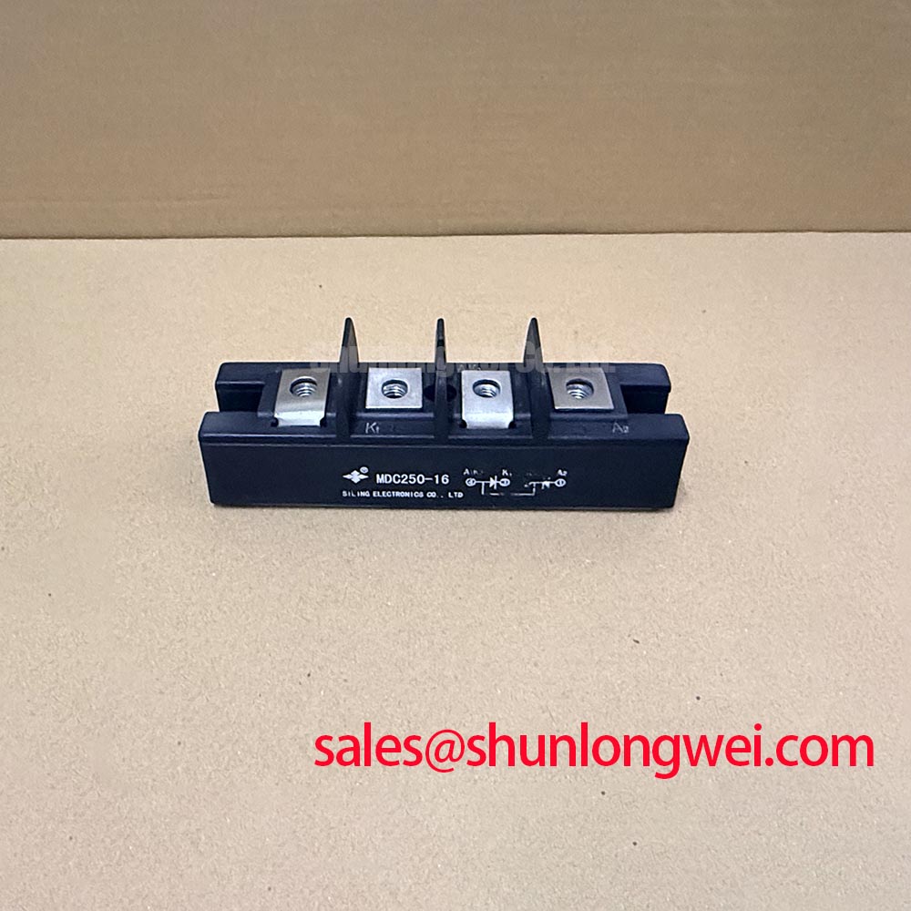
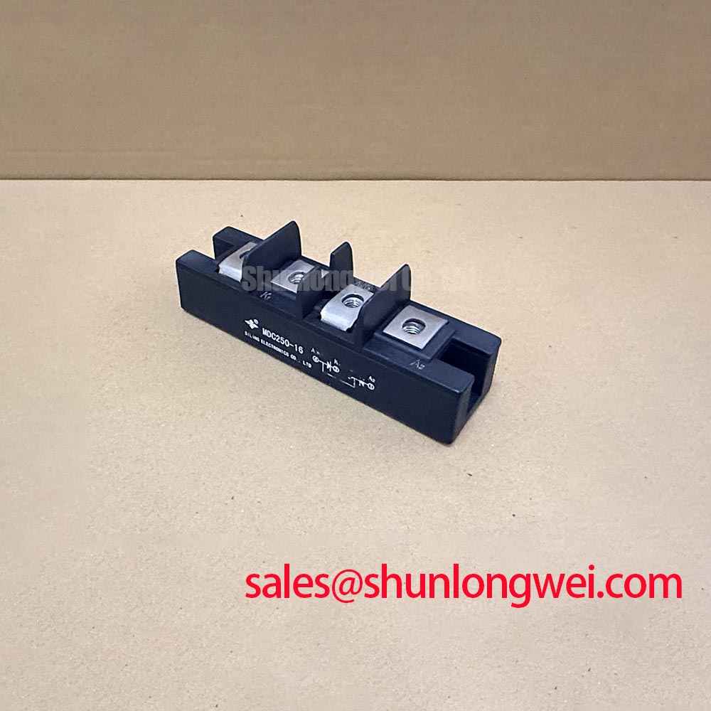
With the power stage isolated and its DC link discharged, compare the terminal markings on the MDC250-16 with the equipment schematic before connecting a meter. Record diode-mode readings in both polarities with external parallel paths disconnected where practical. A cold reading is useful for comparison with a known-good assembly, but it does not establish reverse-blocking capability or switching performance.
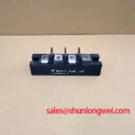
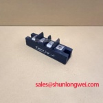
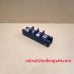
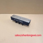
The IXYS MDC250-16 dual diode module has a specified package designation of SOT-227B / TO-240AA. Incoming inspection should distinguish package identification from electrical qualification: terminal arrangement, blocking rating, current-rating conditions, and mounting requirements belong on the acceptance record rather than being inferred from the model suffix.
Separate reverse-recovery current from probe-induced ringing when investigating a commutation fault. As a Design Consideration, evaluate the current waveform alongside the voltage across the commutating diode, using measurement connections appropriate to the circuit potential. Compare captures under consistent load and temperature conditions before attributing a protection trip to the module.
Reverse-recovery peak current, I_rrm, and recovery time, t_rr, require their associated test conditions to be meaningful. Recovery softness describes the shape of the current decay; t_rr alone does not establish soft recovery. Do not assign fast-recovery behavior to the MDC250-16 without an applicable manufacturer specification. For bench acceptance, retain polarity checks and switching qualification as separate records.
Fuse coordination also requires more than a matching current label. As an Engineering Recommendation, compare the protective device’s total clearing I²t with the semiconductor’s applicable withstand specification, accounting for fault voltage, initial temperature, and the specified pulse conditions. Keep that comparison attached to the equipment protection record rather than treating a continuity test as evidence of fault survival.
💡 Bench Tip: Disconnect external parallel paths before comparing cold diode-mode readings, because surrounding circuitry can mask the module’s own conduction pattern.
Assembly Integrity & Layout Architecture: Assessing Rectifier Compatibility and Line Filtering for MDC250-16
Identify which stage controls the rectifier firing angle before interpreting changes in DC output or input current. A dual diode module has no commanded firing angle of its own; phase-angle behavior belongs to the controlled devices and their circuit topology. As a Design Consideration, assess power factor and reactive demand at the converter input under the actual conduction regime, rather than assigning a universal angle-to-output relationship to this module.
For a medium-frequency induction melting or hardening furnace repair, engineers should evaluate the MDC250-16 against the installed rectifier schematic, terminal connections, cooling arrangement, and protection requirements. The DD89N12K-K is a comparison reference, not an established replacement; the following checks define the evidence needed before considering interchangeability.
| Comparison item | MDC250-16 | DD89N12K-K comparison requirement |
|---|---|---|
| Package designation | SOT-227B / TO-240AA | Match outline, mounting features, and terminal positions |
| Voltage, current, recovery, and surge ratings | Consult applicable manufacturer datasheet | Compare numerical limits and their test conditions |
| Circuit compatibility | Verify terminal polarity against the equipment schematic | Establish matching internal connection and external wiring |
| Thermal and mechanical fit | Check the assembly drawing and cooling interface | Compare thermal requirements and fastening instructions |
Where the schematic includes a separate controlled or auxiliary power stage, the PHT308C reference can support a stage-by-stage review without implying interchangeability. Line filtering and harmonic mitigation remain system-level functions. The background on ferrite core materials for switching power supplies explains magnetic-material considerations, but does not specify a filter for the MDC250-16 or establish equipment EMC compliance.
Assembly Integrity & Layout Architecture: Implementing Junction-to-Heatsink Heat Dissipation for MDC250-16
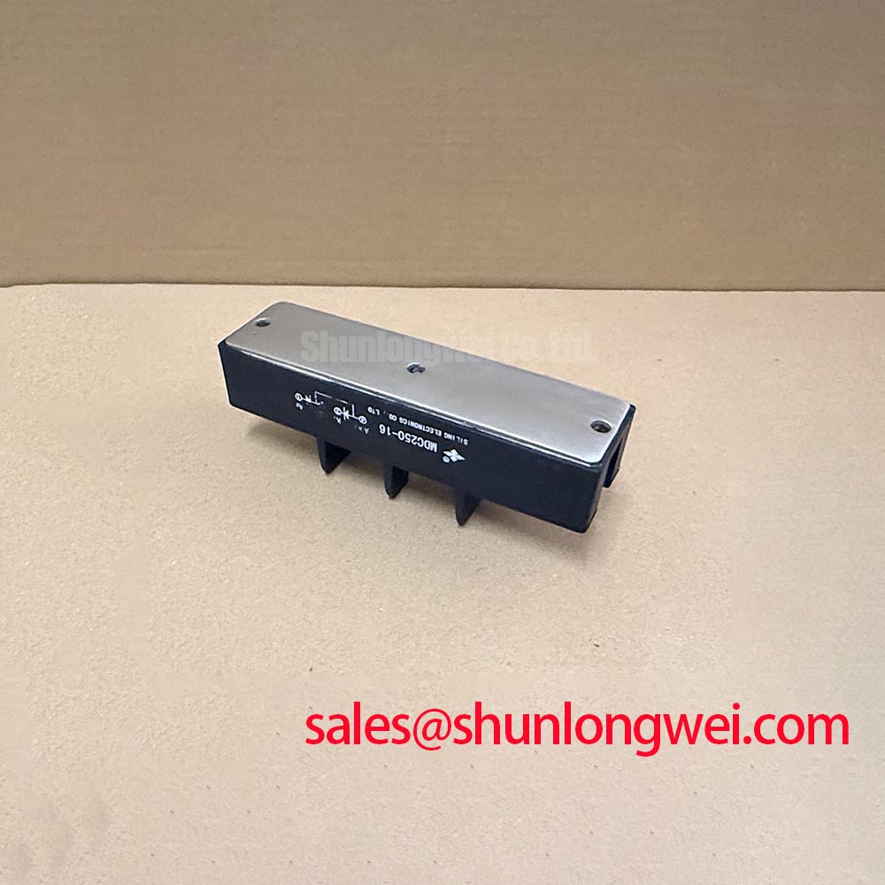
Inspect the heatsink contact surface and fastening arrangement before reinstalling the module. As a Design Consideration, remove interface contamination, check for mechanical interference, and support connected conductors so they do not load the terminals or twist the package during tightening.
Junction-to-case thermal resistance describes only part of the heat path. Interface resistance and heatsink performance must also be included when assessing junction temperature. Use the applicable transient thermal data for pulsed operation; a steady-state thermal resistance should not be treated as a complete description of short-duration heating. Neither a copper baseplate nor a particular internal insulation material should be assumed from the package designation.
Apply thermal interface material and tightening torque according to the applicable module assembly instructions. The engineering objective is continuous contact without package distortion, not maximum bolt force. General background on polytetrafluoroethylene dielectric materials does not establish PTFE construction or an insulation rating for this module.
For broader converter context, Peak Efficiency in Solar and Energy Storage discusses system-level considerations rather than MDC250-16 qualification. At incoming inspection, compare terminal-to-base insulation requirements with the equipment documentation and use the manufacturer-prescribed test method; a handheld resistance reading cannot certify dielectric withstand. Complete the installation record with terminal polarity, interface condition, specified fastening procedure, and temperature observations under controlled loading.