
Content last revised on October 27, 2026
MDC60B-16 Operational Boundaries: Surge-Protection Coordination
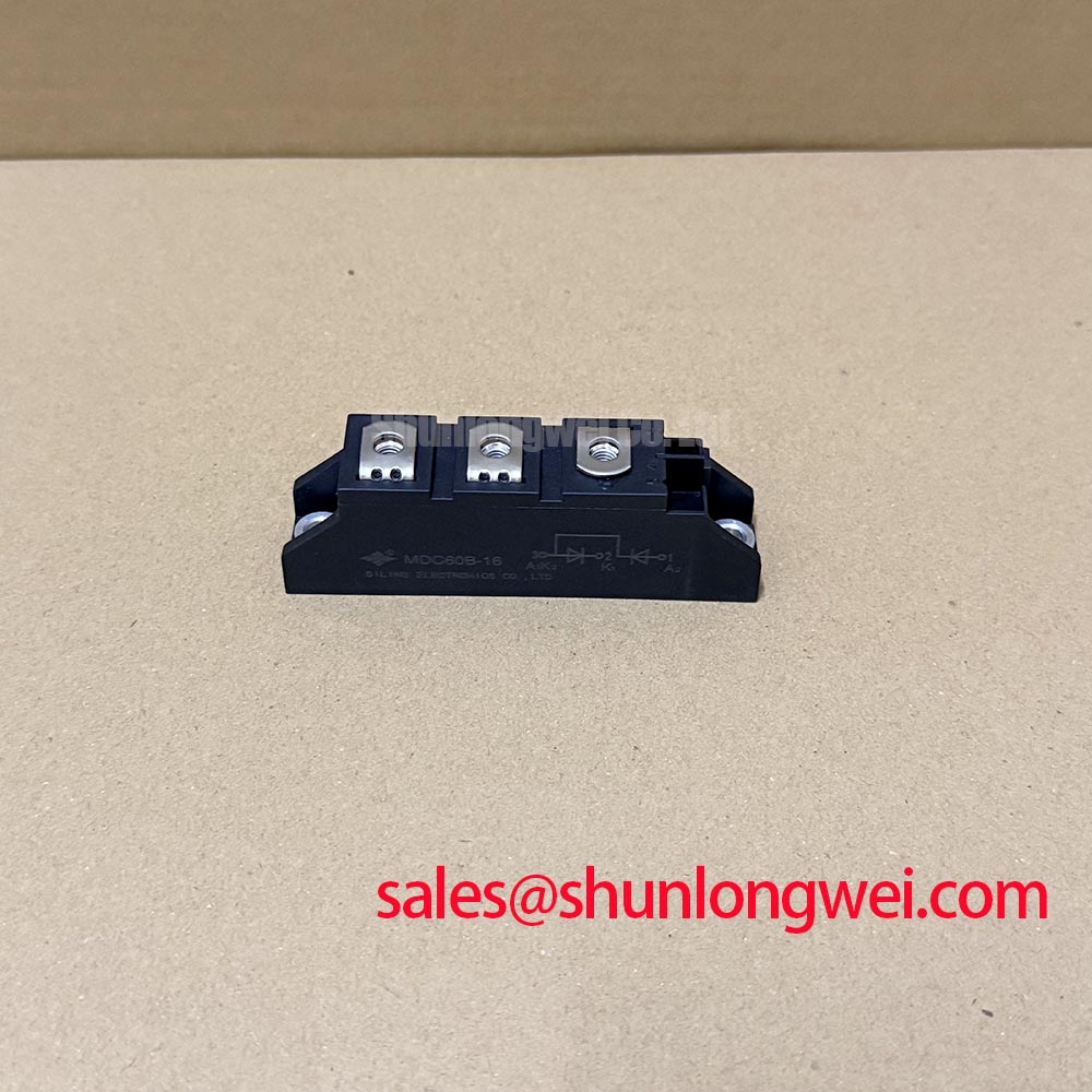
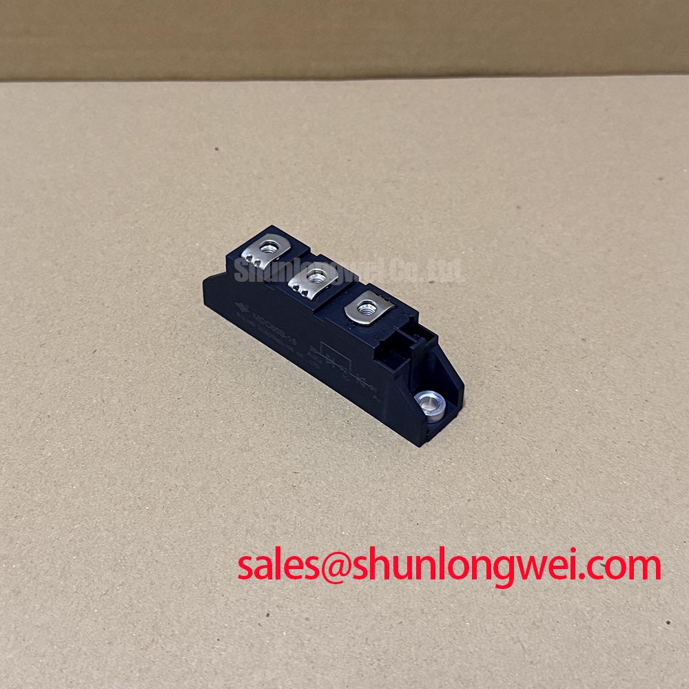
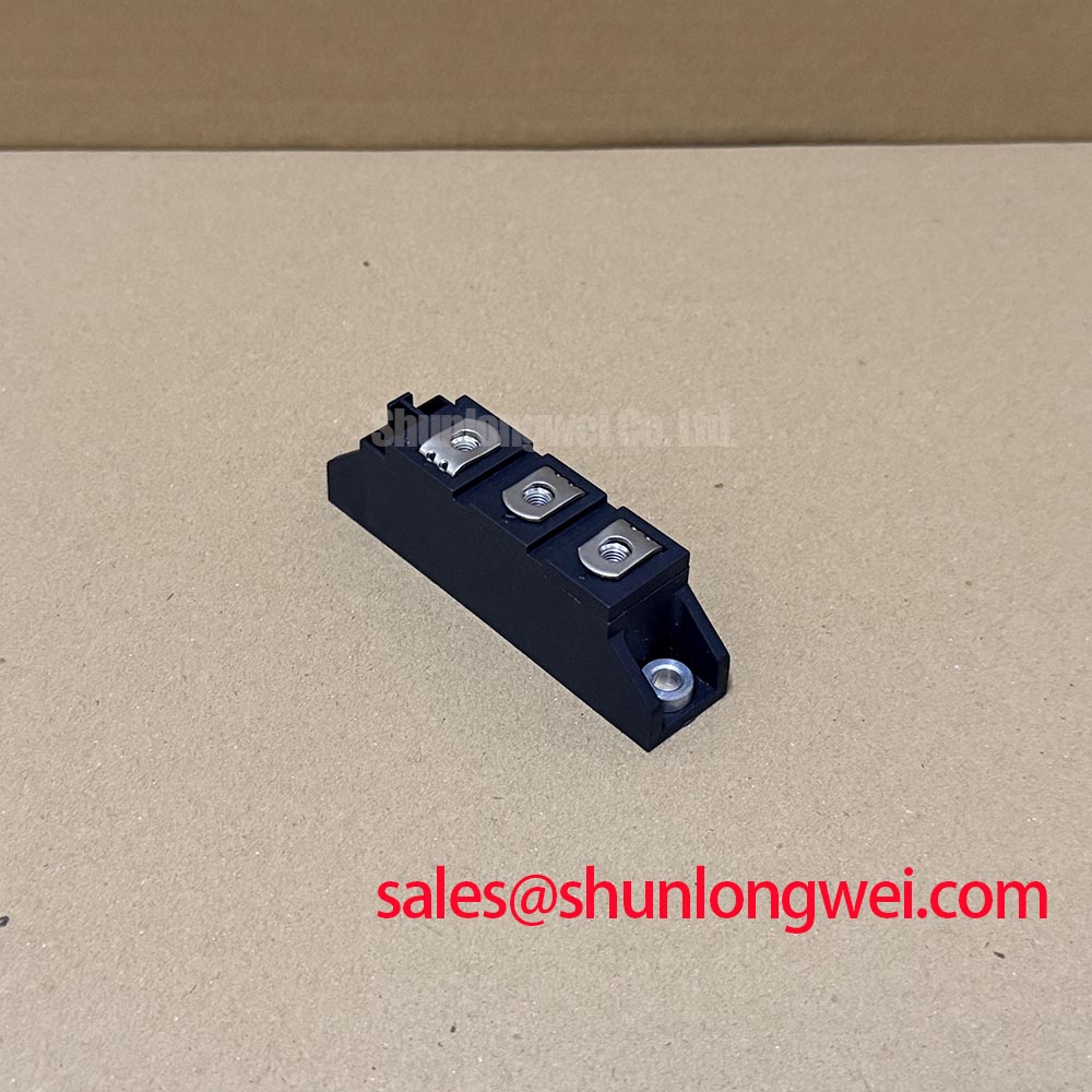
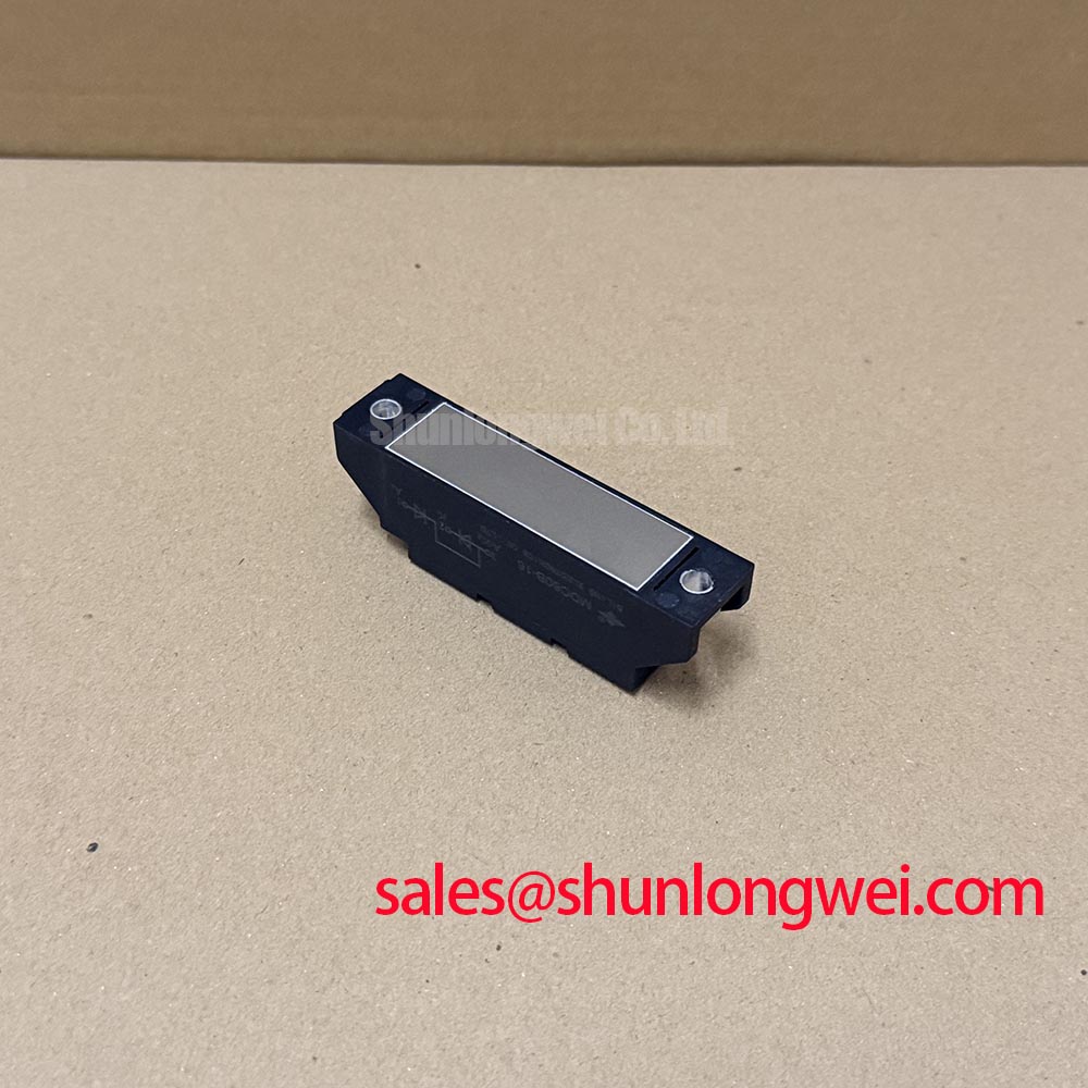
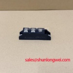
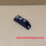
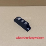
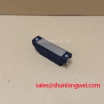
At a failed induction heating power stage, isolate the AC input, confirm the discharge state of the DC link, and inspect the diode module terminals for heat discoloration or loosened conductors before removing the device. The IXYS MDC60B-16 is identified as a dual diode module with a specified industrial voltage rating and specified operating current rating. Its specified package format is SOT-227B / TO-240AA, providing a substantial mechanical interface for industrial rectifier and power conversion assemblies.
For maintenance teams working on medium-frequency induction melting and hardening furnace supplies, the device should be evaluated against the original rectifier topology, fuse coordination, terminal arrangement, and thermal path. The module’s voltage and current ratings must be matched to the equipment documentation and operating waveform rather than inferred from the package designation. The same review should include busbar spacing, enclosure contamination, cooling conditions, and the condition of the gate or control-side circuitry connected to the rectifier stage.
Primary surge protection must be coordinated so that spark gaps, MOVs, input fuses, and the diode junctions respond in a controlled sequence during an abnormal line event. IEC 61000-4-5 test conditions are useful for evaluating the wider equipment assembly, but the protection network remains a system-level design responsibility rather than an independent rating of the MDC60B-16.
During service analysis, compare the installed MOV voltage class and energy capability with the actual AC input arrangement, transformer impedance, and expected surge exposure. An MOV that clamps too aggressively can create unnecessary leakage or thermal stress during normal operation, while an unsuitable clamping level may leave the rectifier exposed to excessive transient voltage. RC suppression placed ahead of the rectifier should be reviewed for pulse energy, repetitive duty, and physical placement near the disturbance source.
Fuse selection should be checked against the manufacturer’s published I²t coordination information for the relevant device family and circuit topology. The fuse must interrupt fault energy before the semiconductor junction reaches a destructive condition, while avoiding nuisance operation during normal charging or current pulses. Inspect the fuse holder, bus connections, and laminated conductors as well as the fuse element; a high-resistance connection can alter the intended protection behavior.
For replacement work, confirm the terminal names and electrical orientation against the original schematic before tightening conductors. SOT-227B / TO-240AA mounting hardware should provide even clamping and a clean thermal interface. ⚠️ Field Alert: apply only the assembly torque specified for the actual mounting hardware and avoid pulling power cables sideways against the module terminals.
MDC60B-16 Operational Boundaries: RC Snubber Network Design
An RC snubber is selected by observing the switching node, identifying ringing frequency and overshoot, and then validating resistor pulse loading and capacitor voltage stress under the real operating waveform. The purpose is to limit unwanted dv/dt coupling and reduce the likelihood of spurious conduction or localized heating at the rectifier junctions. The final R and C values depend on the circuit inductance, commutation path, supply impedance, and switching duty; they should be tuned from measured behavior rather than copied from an unrelated converter.
Series saturable reactors can also influence di/dt during high-current commutation. Their effectiveness depends on core behavior, pulse width, reset conditions, and the actual current profile. When investigating an overheated MDC60B-16, compare both forward current sharing and commutation behavior. A snubber that reduces voltage ringing may still leave excessive current concentration if the conductor layout or reactor placement is asymmetrical.
Keep the snubber loop physically short and return it to the intended power nodes. Long flying leads add inductance and can move the suppression network away from the junctions it is intended to protect. Engineers evaluating an adjacent rectifier stage may also review the neutral DD241S12 reference as part of the broader supply topology, without treating it as an automatic substitute for the IXYS module.
Gate or control-board isolation can be affected by common-mode transients generated elsewhere in the power assembly. Non-overlap timing remains important in bridge arrangements; the general principle is described in Dead-Time Insertion and Non-Overlap Gate Driving in H-Bridges. For fast diode technologies used elsewhere in the same cabinet, the Wolfspeed Silicon Carbide Schottky Diodes technical material offers useful background on high-speed power switching behavior.
MDC60B-16 Thermal-Electrical Behavior: AC-to-DC Transfer Characteristics and Practical Tuning
Firing-angle control changes the rectifier’s average DC output, displacement power factor, reactive demand, and harmonic current profile. When an AC-to-DC stage containing the MDC60B-16 also uses controlled switching devices, record the actual line voltage, load current, firing angle, DC output, and device temperature at each operating point. The resulting operating map is more useful than a nominal calculation because transformer impedance, furnace load variation, and commutation overlap affect the transfer behavior.
In a phase-controlled converter, lower firing angles generally produce higher average output, while advanced firing angles approaching the upper control range reduce useful DC transfer and can make reactive power demand more significant. Harmonic mitigation should therefore be assessed at the equipment input with the intended reactor, filter, and transformer arrangement installed. The diode module rating alone does not establish compliance with an EMC limit.
Thermal verification should follow the complete path from junction to case, mounting interface, heatsink, and airflow or liquid cooling system. Check that parallel current paths are geometrically balanced where multiple devices are used, because unequal conductor impedance can produce unequal static and dynamic sharing even when the components have similar ratings. A practical comparison with the larger MDC300-16 may assist a neutral mechanical and electrical fit review, but the original circuit duty and protection coordination must determine suitability.
For high-power inverter and energy-conversion maintenance teams, the Peak Efficiency in Solar and Energy Storage reference provides additional context for bus structure, switching stress, and efficiency evaluation. The MDC60B-16 should be released back into service only after terminal polarity, insulation clearances, fuse coordination, cooling contact, and measured AC-to-DC behavior agree with the equipment design record.