



Content last revised on September 18, 2026
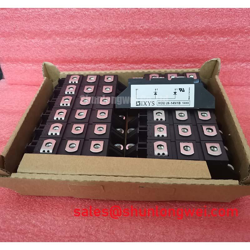
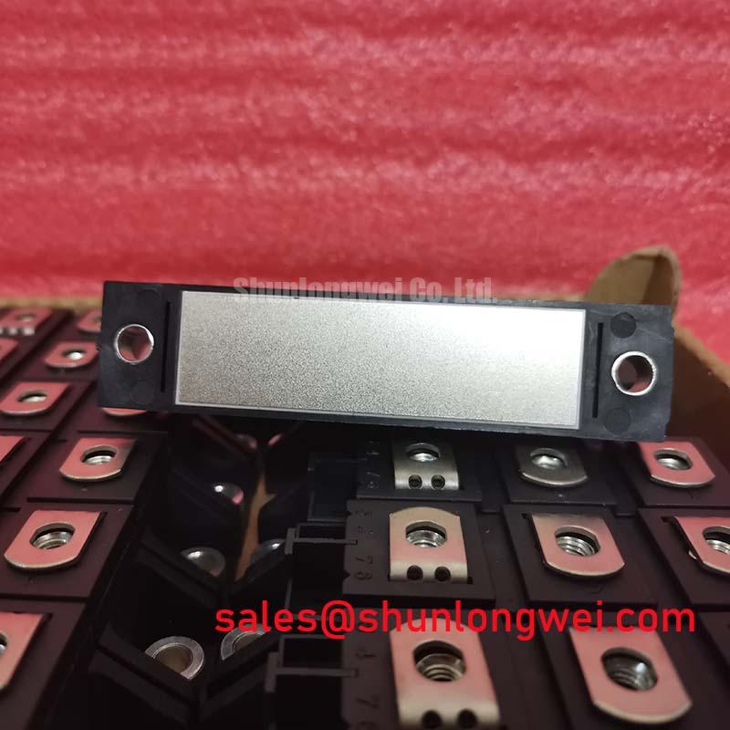
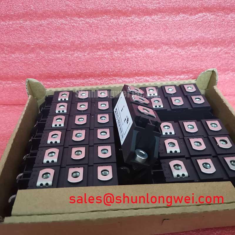
Before connecting the replacement, isolate the assembly, inspect the module housing and terminals, then confirm the nameplate limits against the original circuit documentation: MDD26-14N1B is an IXYS Dual Diode Module with an official rated voltage of 1400.0 V, an official rated current of 26.0 A, and a module-style package.
For incoming inspection, record the terminal markings and compare the diode paths with a known-good reference unit. A digital multimeter in diode-test mode can help identify open or shorted junction behavior, but the measured forward reading depends on the test current, temperature, lead configuration, and the meter itself. The reading should therefore be treated as a cold-state comparison rather than an undocumented pass or fail threshold. High-voltage insulation testing and powered verification require a controlled test procedure based on the equipment manufacturer's limits.
| Parameter | Official specification |
|---|---|
| Manufacturer | IXYS |
| Part number | MDD26-14N1B |
| Product category | Dual Diode Module |
| Rated voltage | 1400.0 V |
| Rated current | 26.0 A |
| Package | Module |
MDD26-14N1B Thermal-Electrical Optimization: Type-2 Coordination: Sub-Cycle Dead-Short Practical Tuning
In a grid-tied static Var compensator or thyristor-switched capacitor assembly, the dual diode module can sit in a high-energy rectification or freewheeling path where a short circuit may expose the semiconductor junction to a rapid current rise. The protection review should begin with the actual circuit topology, conductor impedance, prospective fault current, fuse clearing behavior, and the manufacturer's documented surge and I²t limits. The supplied product data confirms the 1400.0 V voltage class and 26.0 A current class, but it does not establish a fuse coordination table, repetitive surge-current rating, or permissible fault energy.
For that reason, a semiconductor fuse should not be selected from the nominal current rating alone. The system engineer should obtain the applicable IXYS datasheet revision and compare its non-repetitive surge capability and I²t withstand data with the fuse manufacturer's clearing I²t under the intended voltage and prospective fault conditions. The coordination target is to interrupt the fault before the diode junction and package connections exceed their documented limits. Any conclusion about sub-cycle protection remains a system verification result, not an automatic property of the module.
During replacement, clean the mounting surface, preserve the original terminal arrangement, and inspect busbar pressure points for discoloration or looseness. The mounting method, heatsink flatness, interface material, and fastening torque should follow the applicable IXYS mechanical documentation or the original equipment service specification. Bench Tip: Keep the module electrically isolated during cold-state checks, use ESD precautions, and compare all diode-path readings with a documented known-good reference before applying power.
Preventing Spurious Faults: Non-Repetitive Surge On-State Current Guidelines for MDD26-14N1B
Capacitor switching and controlled rectification can produce short-duration current pulses that are materially different from the steady operating current. In an SVC or thyristor-switched capacitor installation, review the switching sequence, capacitor precharge condition, source impedance, line phase relationship, and any residual charge before assessing stress on the diode module. The 26.0 A value is an official rated current supplied for this product page; it should not be reinterpreted as an available 10 ms surge-current rating.
The correct evaluation requires the relevant IXYS electrical characteristics, including any published non-repetitive surge-current and I²t values, together with the measured or calculated current waveform in the installed equipment. The engineer should verify reverse-recovery behavior and junction-temperature margin before reverse voltage is reapplied and should check whether repeated switching pulses create a thermal condition different from a single event. A waveform that appears acceptable during one bench cycle may need additional review when the capacitor bank, firing sequence, and cooling conditions are changed.
Use a current probe and an appropriately rated differential voltage probe when validating the switching path. Capture the first current pulse, the recovery interval, and the reverse-voltage transition at the module terminals rather than relying only on controller feedback. If the observed waveform differs from the known-good installation, investigate gate or trigger timing, wiring inductance, capacitor condition, and measurement-loop pickup before assigning a single cause.
For related power-semiconductor context, the Shindengen power semiconductor reference provides industry information on module and diode technologies. It does not replace the IXYS documentation required for the MDD26-14N1B electrical limits.
MDD26-14N1B Circuit Protection & Reliability: Calibrating IEC 61000-4-5 Industrial Surge Immunity
An IEC 61000-4-5 immunity test concerns the complete equipment port, protection network, wiring, grounding, and test configuration. The diode module itself should not be described as independently certified for an EMC or surge-immunity standard. When this part is evaluated in an AC input or capacitor-switching branch, the system designer should map the surge-current path through the upstream fuse, disconnect, wiring inductance, MOV network, damping components, and semiconductor junctions.
MOV selection is determined by the system's continuous operating voltage, temporary overvoltage exposure, surge waveform, energy capability, leakage requirements, and coordination with upstream protection. The MDD26-14N1B product information supplied here confirms a 1400.0 V rated voltage, but it does not specify a suitable MOV voltage, clamping level, energy rating, or RC snubber value. Those values must be selected from the complete circuit conditions and then verified with surge testing.
An RC network may reduce ringing and limit repetitive voltage stress, but its resistor pulse capability, capacitor insulation rating, dissipation, layout, and interaction with the source impedance require equipment-level validation. Keep the high-current protection loop compact and inspect the terminal connections after testing. Designers evaluating the broader relationship between semiconductor selection, gate or trigger control, thermal paths, and circuit topology can consult IGBT Design & Integration as a general engineering reference; it is not a substitute for the IXYS part documentation.
Where a repair requires a different current or voltage class, the alternative must be checked against the original mechanical footprint, terminal polarity, thermal interface, isolation requirements, and protection coordination. The 2DI75A-140 may be reviewed as a separate compatible-device candidate, but equivalence should be established from its own datasheet and the equipment manufacturer's service requirements rather than assumed from product category alone.
Benchtop Waveform Tuning: Mitigating Stress via Phase-Controlled Rectification, Firing Angle on MDD26-14N1B
When a controlled rectifier or capacitor-switched branch is tested on the bench, begin with the original firing sequence and confirm that the module terminals are connected according to the equipment schematic. The MDD26-14N1B is documented here as a 1400.0 V, 26.0 A IXYS dual diode module; the product data supplied for this page does not define a firing-angle operating range, transfer curve, power-factor value, reactive-power limit, or thermal derating curve.
As firing delay increases, the conduction interval and source-current waveform change, which can affect DC output, displacement power factor, harmonic current, capacitor stress, and transformer loading. These effects should be measured at the actual installation using synchronized voltage and current channels. The system engineer should verify peak terminal voltage, current pulse width, repetition rate, heatsink temperature, and recovery behavior against the applicable IXYS ratings and the equipment design limits.
For a high-power braking or energy-absorption branch connected to a rectified DC link, the diode module's role must be separated from the braking resistor's energy duty. The resistor, switching device, fuse, DC-link capacitor, and cooling system each have independent limits. Do not infer braking-energy capacity from the diode module's 26.0 A rating. Where the circuit also uses a complementary controlled power stage, the SKKT 106B14E can be reviewed as a related topology component, subject to its own voltage, current, trigger, thermal, and mechanical specifications.
During final validation, compare cold-state diode checks with post-test readings, inspect terminal temperature balance, and review the captured waveform for abnormal ringing or unexpected reverse-voltage recovery. Any replacement decision should preserve the documented voltage class, current class, package arrangement, and protection coordination of the original installation.