
Content last revised on October 29, 2026
MDS300-18 Three-Phase Diode Bridge Rectifier Overview
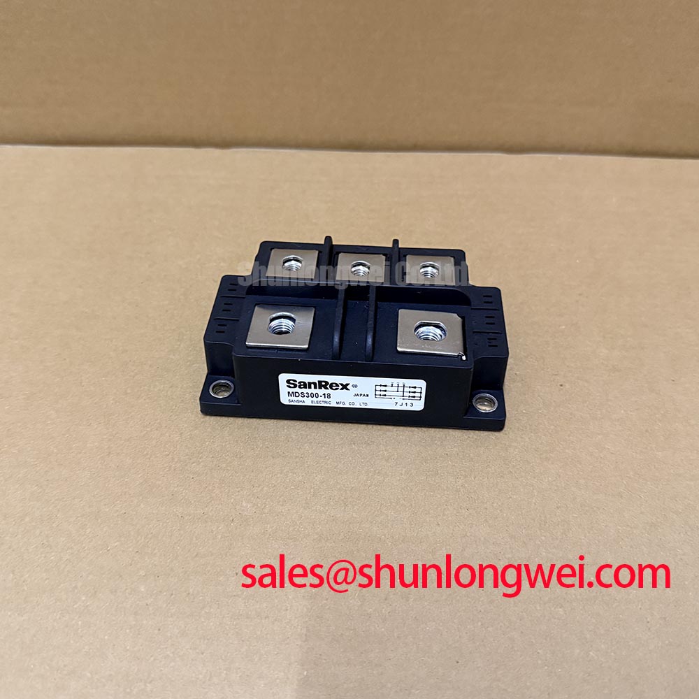
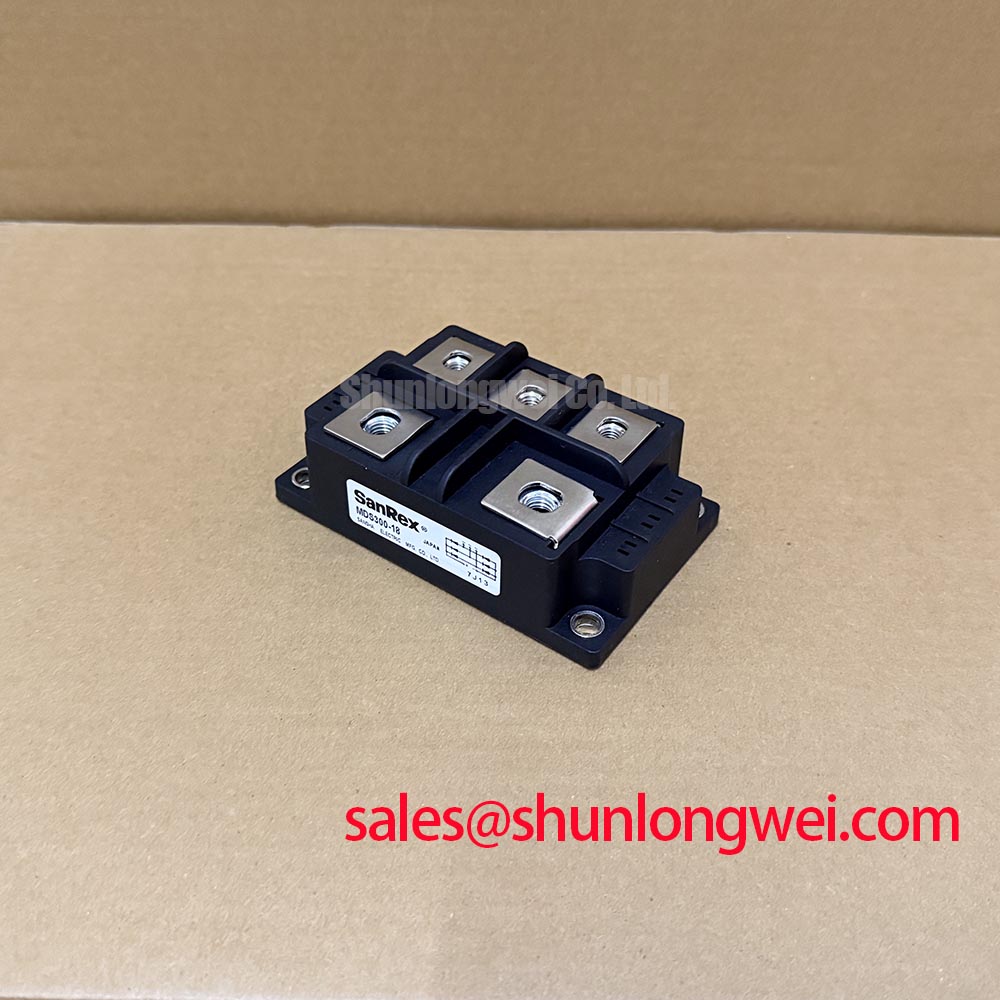
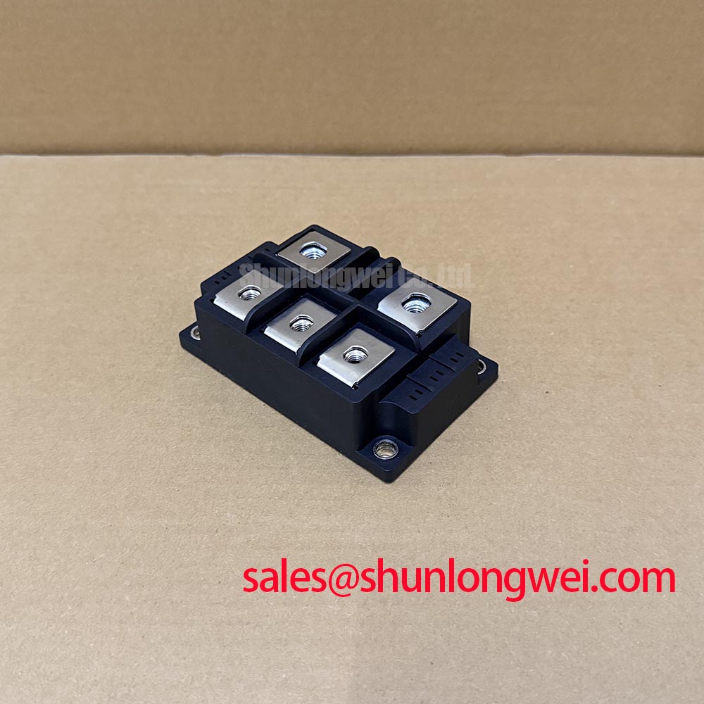
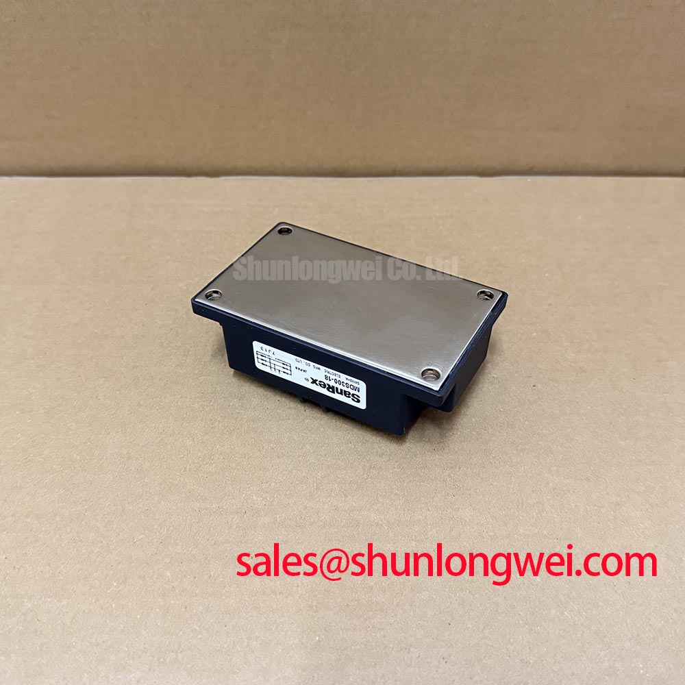
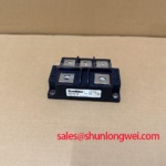
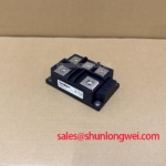
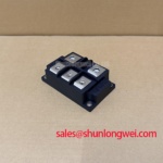
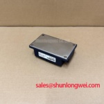
When a high-current rectifier cabinet reports abnormal DC output, isolate the AC input, discharge stored energy, and verify the absence of voltage before inspecting the bridge terminals, bus connections, cooling path, and fuse condition or applying test voltage. The MDS300-18 is a SanRex (Sansha Electric) three-phase diode bridge rectifier module, specified at 1800 V and 300 A. Its package is identified as a Three-Phase Rectifier Case for industrial power conversion assemblies.
For a high-current green hydrogen electrolyzer DC power rectifier, the module may be evaluated as part of the three-phase AC conversion stage. The final suitability assessment remains dependent on the complete thermal design, bus structure, protection network, duty cycle, and the rectifier manufacturer’s installation requirements.
| Manufacturer | SanRex (Sansha Electric) |
| Part Number | MDS300-18 |
| Category | Bridge Rectifier Module |
| Topology | Three-Phase Diode Bridge Rectifier |
| Voltage Rating | 1800 V |
| Current Rating | 300 A |
| Series | Standard |
Transient Dynamics & Electrical Design: Mitigating DC Ripple Currents in MDS300-18 Rectifier Systems
A six-pulse bridge is the normal starting point for three-phase diode rectification, while a twelve-pulse arrangement can reduce characteristic low-order ripple and input harmonic content when the transformer and phase displacement are designed as a matched system. At kiloampere-level DC output, the MDS300-18 should be assessed as one part of that topology rather than as an isolated current source.
When two rectifier bridges operate with parallel DC outputs in a twelve-pulse configuration, an interphase transformer can help share current between bridge outputs while limiting circulating current and unequal thermal loading. Designers should verify the transformer ratio, phase displacement, bus symmetry, and the actual current waveform during commissioning. The bridge terminal layout should follow the mechanical and electrical arrangement specified for the equipment, with short, balanced connections used to limit stray inductance and switching overshoot.
DC ripple also affects capacitor heating, busbar vibration, and the operating stress imposed on downstream converters. If a controlled rectifier or power conditioning stage is placed ahead of the bridge, its firing strategy and conduction interval should be coordinated with the transformer and load profile. The MDS300-18 data should be used for the voltage and current identity of the replacement unit, while ripple performance remains a system-level result.
For a complementary rectification stage in a larger power assembly, engineers may also review the SKD116/18-L75 as a separate device reference. It should not be treated as an automatic substitute for the MDS300-18.
Field Diagnostics & Commissioning: Semiconductor Protection Fuse Selection in MDS300-18 Topologies
Fuse coordination must compare the semiconductor fuse clearing characteristic with the diode bridge’s permitted surge and short-circuit withstand data. The correct review uses the fuse manufacturer’s I²t curve, prospective fault current, circuit impedance, and the rectifier manufacturer’s published withstand limits. A fuse with a suitable voltage label alone does not establish protection for a dead-short event.
During commissioning, record the fuse class, rated voltage, interrupting capability, pre-arcing I²t, total clearing I²t, and connection arrangement. Compare those values with the protection table used by the equipment designer. If the system documentation does not provide a coordinated combination, the electrical protection engineer should complete the assessment before energization rather than infer suitability from the module’s 300 A rating.
Terminal preparation is equally important. Clean contact surfaces, correctly sized lugs, controlled conductor routing, and the manufacturer’s specified tightening torque help prevent localized resistance heating. Recheck terminal condition after the initial thermal run and inspect for discoloration, loosening, or uneven cable loading.
Maintenance Note: Isolate and discharge the assembly and verify the absence of voltage before removing any cable or fuse. After reassembly and safe return to service, verify that the cooling path and terminal temperature remain stable under the intended load.
MDS300-18 Circuit Protection & Reliability: AC Line Surge Immunity and Lightning Transients
AC input protection should be arranged around the actual line-to-line and line-to-earth exposure of the installation. MOV selection requires evaluation of continuous operating voltage, temporary overvoltage, energy absorption, fault disconnection, and the surge environment defined by the applicable system standard. An MOV is not a substitute for a semiconductor fuse or for correct grounding and bonding.
RC snubber networks can reduce high-frequency ringing when their placement, damping behavior, and voltage rating match the bridge and wiring inductance. The network should be validated at the rectifier terminals during representative energization and fault-clearing tests. Keep the protection loop physically compact, separate high-current paths from sensitive control wiring, and verify that enclosure condensation does not compromise insulation spacing.
Industrial drive boards placed near the rectifier may use optocouplers or digital isolators, but their common-mode transient immunity must be checked against the measured switching environment. Gate-drive design guidance can be reviewed through Precision Gate Drive Design, while the MDS300-18 itself remains a diode bridge and does not contain a gate-drive interface.
For technology comparison, HEMT channel behavior is described in this HEMT reference; that channel mechanism is distinct from the conduction behavior of a three-phase diode bridge. Any surge suppressor, snubber, or isolation choice should be confirmed through measured voltage and current waveforms at the installed module.