
Content last revised on April 2, 2026
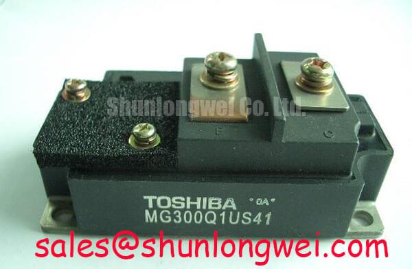
Toshiba MG300Q1US41: 1200V 300A High-Speed Single IGBT Module
The MG300Q1US41 by Toshiba delivers exceptional switching efficiency in high-power electronics through rapid 0.5µs turn-off times, minimizing dynamic losses in demanding 1200V motor control systems. Designed specifically as a single-element N-Channel IGBT, its core specifications include a robust 1200V VCES rating, 300A of continuous collector current, and a maximum power dissipation threshold of 2000W. Key benefits include: Minimizes high-frequency switching loss; simplifies custom power phase layout. Why choose a single-element IGBT module over an integrated pack? A single-switch configuration provides maximum physical and electrical layout flexibility for constructing custom high-power inverter topologies, allowing engineers to distribute thermal loads precisely. What defines the switching performance of this module? Its 0.5µs maximum fall time drastically reduces dynamic turn-off losses. For heavy-duty industrial drives prioritizing dynamic efficiency and thermal margin, this 300A module is the optimal choice.
Key Parameter Overview
Decoding the Specs for Optimal Switching Efficiency
Understanding the delicate balance between high voltage handling and switching speed is critical for robust power converter design. Below is the functional grouping of the essential MG300Q1US41 specifications.
| Maximum Ratings | |
|---|---|
| Collector-Emitter Voltage (VCES) | 1200V |
| Continuous Collector Current (IC) | 300A |
| Maximum Power Dissipation (Pc) | 2000W |
| Dynamic Performance | |
| Fall Time (tf) | 0.5µs (Max) |
| Reverse Recovery Time (trr) | 0.5µs (Max) |
| Static Characteristics | |
| Collector-Emitter Saturation Voltage (VCE(sat)) | 4.0V (Max) |
| Isolation | Isolated Baseplate |
Download the MG300Q1US41 datasheet for detailed specifications and performance curves.
To grasp the engineering value, think of the 0.5µs fall time like a high-performance brake system on a race car; it stops current flow almost instantly, preventing excess heat buildup during high-frequency electrical transitions.
Application Scenarios & Value
Achieving System-Level Benefits in High-Power Motor Control
Engineers designing megawatt-scale Variable Frequency Drives (VFD) or high-capacity UPS systems frequently face challenges with thermal management during high-frequency PWM switching. In a typical PWM inverter stage, slow turn-off times lead to massive switching losses, stressing the heatsink and severely reducing overall system efficiency. The MG300Q1US41 directly mitigates this physical limitation. By leveraging its maximum 0.5µs fall time (tf) and 0.5µs reverse recovery time (trr), the module drastically cuts dynamic power dissipation during the critical commutation phases. When driving heavy inductive loads typically found in robust servo drives or industrial traction systems, the 300A rating ensures steady, reliable operation without premature thermal degradation. Furthermore, compliance with industrial EMC standards, such as IEC 61800-3, is heavily influenced by how cleanly an IGBT switches; the controlled characteristics of this module help maintain cleaner electromagnetic footprints. While the MG300Q1US41 excels in modular, custom single-switch layouts, engineers seeking integrated high/low side configurations for rapid assembly might evaluate the CM300DY-24H, which offers comparable voltage and current ratings in a dual-module package.
Technical Deep Dive
A Closer Look at the Isolated Packaging and Dynamic Response
The fundamental architecture of the MG300Q1US41 pairs high input impedance with an advanced enhancement-mode N-Channel design, which significantly simplifies the gate drive circuit requirements compared to older bipolar transistor technologies. A critical mechanical and thermal design feature is its fully isolated baseplate. The isolated baseplate acts much like a thermal firewall, ensuring that the active silicon chips transfer up to 2000W of dissipated power (Pc) directly to the external heatsink without passing hazardous electrical noise or high voltage to the metal chassis. This internal isolation eliminates the need for complex, fragile external insulating pads, thereby reducing parasitic capacitance and lowering the critical risk of dielectric failure in high-voltage industrial environments. To fully utilize this high-power isolation capability, evaluating and applying proper thermal interface materials is absolutely essential for long-term reliability. For further advanced reading on optimizing these interfaces, consult our engineering resources on mastering IGBT thermal management or explore the detailed physics of how an IGBT works to maximize your voltage-controlled switching efficiency.
Frequently Asked Questions
Addressing Core Engineering Inquiries
- How does the 0.5µs fall time of the MG300Q1US41 impact PWM inverter stage design?
The rapid 0.5µs fall time substantially reduces the switching energy (Eoff) generated per cycle. This enables higher operating switching frequencies within the PWM inverter stage, which in turn shrinks the physical size of required magnetic filter components and significantly improves the output current waveform quality to the motor. - What is the primary advantage of the single-element isolated case in this Toshiba module?
The isolated baseplate electrically separates the 1200V collector potential from the physical heatsink structure. This simplifies the mechanical mounting process, improves thermal transfer by allowing direct metal-to-metal contact with grounded cooling plates, and greatly enhances overall operator safety in multi-module, high-density power banks.
For engineers evaluating thermal margins and dynamic losses, contact our technical team to request pricing and stock availability for your next high-power converter design.