

Content last revised on October 11, 2026
MG50G6ES50 Thermal-Electrical Optimization: Dynamic Gate Impedance Control for Robust Practical Tuning
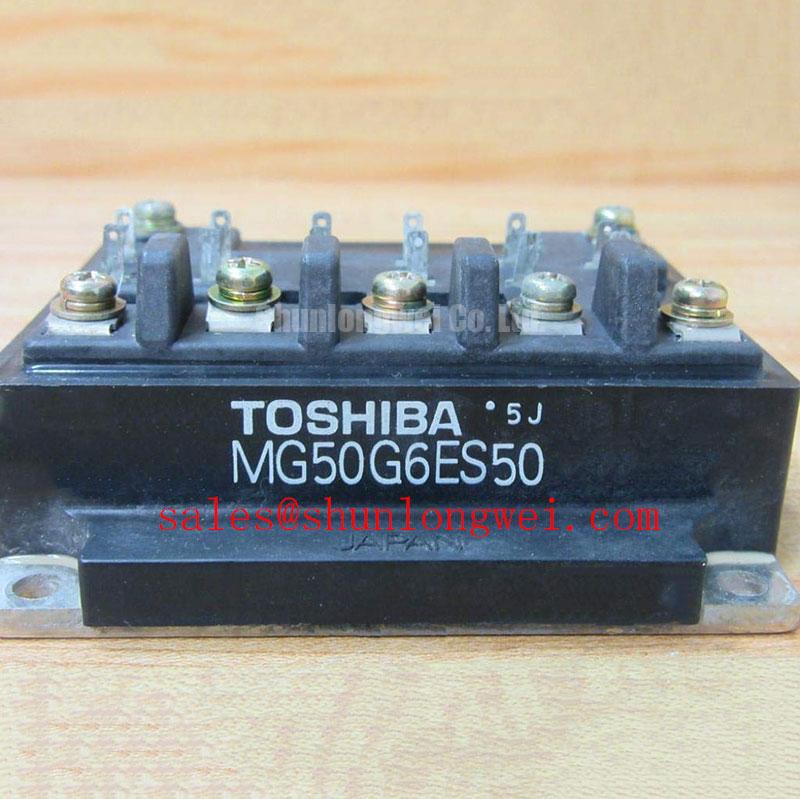
I would probe the inactive gate during complementary switching before increasing load, looking for a gate excursion that coincides with the opposite device’s voltage transition. For the MG50G6ES50, this assessment connects gate-drive behavior to its 600.0 V voltage rating without treating an observed current spike as proof of shoot-through. Diode recovery, probe pickup, and genuine unintended turn-on require different corrective actions.
Design Consideration: Miller capacitance couples a changing collector voltage into the gate circuit. A short gate-return path and adequate driver sinking capability help limit the resulting gate excursion. Designers should evaluate an active Miller clamp where the driver architecture supports it, checking its engagement timing and connection inductance. Negative off-state bias is another system-level option, but its magnitude must follow the permitted gate-voltage limits and measured switching behavior rather than a generic prescription.
Engineering Recommendation: compare gate-emitter voltage, collector-emitter voltage, and current with appropriately rated probes and controlled test energy. Reference the gate measurement close to the device terminals; a remote driver-ground measurement can hide return-path voltage movement. Adjust turn-on and turn-off impedance independently where the circuit permits, then inspect overshoot, ringing, switching loss, and thermal response together. Faster switching is not automatically a better operating point.
Design Consideration: freewheel-diode reverse recovery can contribute to commutation current and high-frequency ringing. Recovery softness describes the shape of that transient, not an independently established feature of this module. Evaluate the installed commutation path across relevant temperature and load conditions. The external discussion of heavy copper PCB construction provides conductor context, but thicker copper alone does not ensure low loop inductance or system EMC compliance.
Field Diagnostics & Commissioning: Pre-Installation Junction Health Check in MG50G6ES50 Topologies
Disconnect the module from parallel circuit paths, verify that stored bus energy has dissipated, and use diode-check mode only after identifying the terminals from the circuit diagram. Compare both measurement polarities across the documented power paths. Where an antiparallel diode is shown, record its directional behavior under consistent meter conditions. A near-short or unexpected asymmetry warrants further investigation; a single forward-voltage reading cannot certify junction health.
Engineering Recommendation: inspect gate-to-emitter behavior with an instrument and test method that respect the gate limits. A multimeter can reveal gross leakage or a short, but it does not establish leakage compliance or dynamic gate integrity. Keep the gate controlled during handling and screening. Treat any “Fo” designation as a schematic-specific signal requiring pin-map confirmation, not as evidence that the MG50G6ES50 includes an integrated fault-output function.
Design Consideration: shorten the commutation loop and keep outgoing and returning bus conductors closely coupled to reduce inductive turn-off overshoot. If the assembly includes a film snubber capacitor, evaluate its actual connection loop rather than its physical proximity alone. Check mounting-surface condition, thermal-interface coverage, and terminal alignment before energization; mechanical strain and poor heat transfer can undermine an otherwise acceptable electrical installation.
Practical tip: Keep the commutation bus layout balanced and compact, then verify collector-voltage headroom with controlled double-pulse measurements before full-load operation.
For replacement assessment in a compact industrial inverter or high-speed CNC spindle drive, compare topology, terminal arrangement, mounting geometry, drive requirements, and cooling conditions against the original assembly. The Toshiba MG400Q1US41 is a separate comparison candidate, not an established drop-in substitute. Design Consideration: long motor cables can create reflected terminal-voltage peaks; evaluate cable characteristics and the existing output-filter arrangement at the motor as well as at the inverter.
MG50G6ES50 Circuit Protection & Reliability: Calibrating SCSOA Overcurrent Protection
Trace the complete overcurrent shutdown path from sensing input to gate discharge before testing the power stage. Include sensor response, filtering, comparator behavior, isolation delay, and driver action. Design Consideration: a short present at turn-on and a fault developing during conduction impose different detection conditions. Where short-circuit capability is documented, protection timing must remain within its limits under the applicable bus voltage, gate drive, and junction temperature. Do not assume a guaranteed short-circuit withstand time if none is specified.
Engineering Recommendation: evaluate desaturation or current-based detection against normal switching transients so that blanking suppresses nuisance trips without concealing a fault. Where supported, staged soft turn-off can reduce inductive overvoltage by controlling fault-current decay. Its timing and impedance remain system-dependent. Review the gate waveform and collector-voltage excursion together, including whether the shutdown circuit maintains a secure off state after the trip.
Design Consideration: semiconductor-fuse coordination requires the protective device’s clearing behavior, prospective fault current, and the assembly’s withstand limits; an I²t comparison alone does not establish protection against module rupture. The welding power supply overview illustrates another inverter context, not MG50G6ES50 application approval. For broader switching and fault-mechanism background, use The Ultimate IGBT Knowledge Base alongside the device documentation, then validate fault shutdown using a controlled, energy-limited test arrangement.