


Content last revised on April 22, 2026
Fuji Electric 6RI100E-080 IGBT Module: An Engineer's Technical Review
Introduction to the 6RI100E-080 Power Module
A Robust, Integrated Solution for Three-Phase Power Conversion
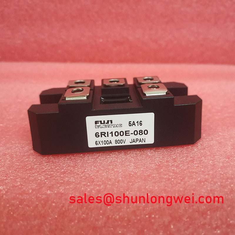
The Fuji Electric 6RI100E-080 is an 800V, 100A six-pack IGBT module designed for reliability in medium-power motor control and power conversion applications. This component integrates a full three-phase inverter bridge into a single, compact package, streamlining system design and assembly. Its core specifications are: 800V VCES | 100A IC | 6 IGBTs in a Bridge Configuration. The key engineering benefits include significantly simplified power stage layout and proven thermal performance for consistent operation. By integrating six IGBTs, the 6RI100E-080 directly addresses the need for a compact power stage in applications like Variable Frequency Drives (VFDs). For cost-sensitive industrial motor drives operating from a 380-480V AC line, this 800V module provides a robust and integrated solution.
Key Parameter Overview
Highlighting Critical Specifications for System Design
The technical specifications of the 6RI100E-080 define its operational boundaries and performance characteristics. The following table highlights the most critical parameters for design engineers evaluating this module for their power systems. Particular attention should be paid to the thermal resistance and saturation voltage, as these directly influence efficiency and thermal management strategies.
| Parameter | Symbol | Conditions | Value |
|---|---|---|---|
| Collector-Emitter Voltage | VCES | VGE = 0V | 800V |
| Gate-Emitter Voltage | VGES | ±20V | |
| Collector Current (DC) | IC | TC = 80°C | 100A |
| Collector Current (Pulsed, 1ms) | ICP | TC = 80°C | 200A |
| Collector Power Dissipation | PC | Per IGBT | 480W |
| Collector-Emitter Saturation Voltage | VCE(sat) | IC = 100A, VGE = 15V | 2.7V (Max) |
| Thermal Resistance (Junction to Case) | Rth(j-c) | Per IGBT | 0.26 °C/W |
| Operating Junction Temperature | Tj | +150°C |
Download the 6RI100E-080 datasheet for detailed specifications and performance curves.
Application Scenarios & Value
System-Level Benefits in Industrial Motor Control and Power Supplies
The 6RI100E-080 is engineered for applications where a balance of performance, integration, and reliability is paramount. Its 6-in-1 configuration makes it an excellent fit for compact three-phase inverter designs, reducing complexity and assembly time compared to using discrete components.
A primary high-fidelity engineering scenario is the development of a Variable Frequency Drive (VFD) for a 15 kW industrial motor. In such a system, the main challenge is managing the power stage efficiently within a constrained enclosure. The 6RI100E-080 directly solves this by providing the complete inverter bridge in one module. This not only saves valuable PCB space but also simplifies the busbar and gate drive layout, which is critical for minimizing stray inductance and ensuring clean switching. The 800V collector-emitter voltage rating provides a sufficient safety margin for systems operating on a 400V or 480V AC line, accommodating voltage spikes that occur during switching events. What is the primary benefit of its 6-in-1 configuration? It simplifies the power stage layout for three-phase inverters.
For systems requiring operation at higher DC bus voltages, such as those found in high-power renewable energy or specialized industrial drives, a module like the FZ400R17KE3 offers a higher blocking voltage capability of 1700V.
Frequently Asked Questions (FAQ) for the 6RI100E-080
What are the implications of the 800V VCES rating for system bus voltage selection?
An 800V VCES provides a robust safety margin for three-phase systems connected to 380V to 480V AC lines. After rectification, this results in a DC bus voltage of approximately 540V to 680V. The 800V rating ensures the device can withstand transient overvoltages from line fluctuations and switching-induced spikes, a crucial factor for preventing IGBT failure in industrial environments.
How does the Rth(j-c) of 0.26 °C/W impact heatsink selection and thermal design?
The thermal resistance, Rth(j-c), is a critical metric that dictates how efficiently heat can be transferred from the IGBT junction to the module's case. A lower value is better. To understand its impact, think of it as the width of a pipe for heat flow; a wider pipe (lower resistance) lets more heat escape easily. The 0.26 °C/W value requires a carefully selected heatsink to maintain the junction temperature below the 150°C maximum under full load, directly influencing the system's overall size and cost.
Is the 6RI100E-080 suitable for high-frequency switching applications like welding?
While the module is robust, its datasheet specifies switching characteristics (turn-on/turn-off times) that are optimized for motor drive frequencies, typically in the range of 2 kHz to 15 kHz. For high-frequency applications like welding or induction heating that often exceed 20 kHz, a module with lower switching losses (Eon/Eoff) would be a more efficient choice to minimize heat generation. This module prioritizes conduction performance and ruggedness over ultra-fast switching.
What is the benefit of the integrated 6-in-1 topology?
The primary benefit is system simplification. It combines the six necessary IGBTs for a three-phase inverter into a single component. This reduces the number of parts to be mounted, simplifies the high-current busbar design, and ensures that the thermal characteristics of all switches are closely matched because they share a common substrate. This leads to more predictable performance and easier implementation of control strategies like Pulse Width Modulation (PWM).
Technical Deep Dive
Analyzing the Module's Construction for Enhanced Reliability
The design philosophy behind the 6RI100E-080 is centered on providing a reliable power switching solution in a standard industrial package. Inside the module, the six IGBT chips and their corresponding freewheeling diodes are mounted on a ceramic substrate, typically Alumina (Al2O3) or Aluminum Nitride (AlN), which provides excellent electrical isolation while facilitating thermal conductivity to the copper baseplate. This construction is foundational to the module's performance.
The thermal pathway is perhaps the most critical aspect of its design. The specified Rth(j-c) of 0.26 °C/W is the sum of all thermal resistances from the silicon chip to the module's mounting surface. Interpreting this value is key: for every watt of power dissipated as heat in an IGBT, the junction temperature will rise by 0.26°C above the case temperature. This parameter is as fundamental to thermal design as Ohm's law is to electrical design. A design that ignores this can lead to thermal runaway and premature failure. The module's internal layout is optimized to balance current sharing and heat distribution among the chips, contributing to its overall operational robustness.
Strategic Fit in System Design
From a strategic perspective, the Fuji Electric 6RI100E-080 represents a workhorse component for established industrial applications. It is best suited for designers who prioritize a proven, integrated solution to accelerate development time for mid-power inverters. While newer technologies may offer lower switching losses, the 6RI100E-080 provides a known quantity in terms of reliability and electrical characteristics, making it a low-risk choice for upgrading existing designs or for new projects where time-to-market and dependability are the primary drivers. For more information on Fuji Electric's power module offerings, their official product series page provides a comprehensive overview.