

Content last revised on October 23, 2026
MMF400Y040DK1B Thermal-Electrical Optimization: Short-Circuit Withstand Limits: Practical Tuning
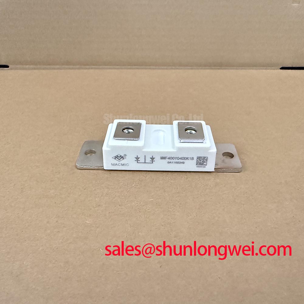
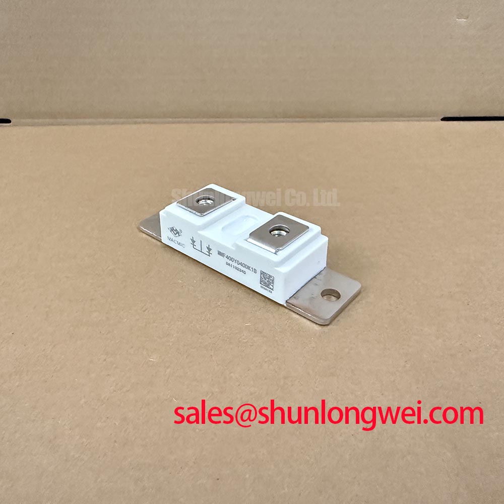
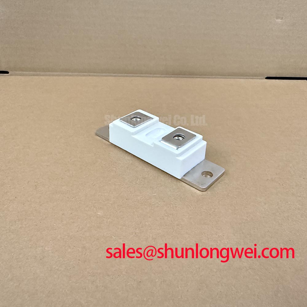
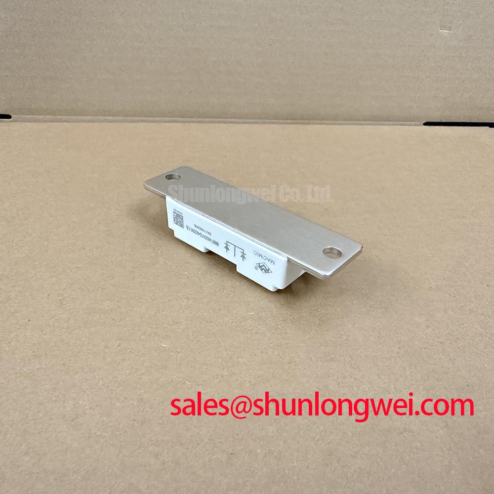
Isolate the power circuit and verify that stored energy has discharged before checking the MMF400Y040DK1B terminal connections, fuse designation, and heatsink contact surface. For this MACMIC diode module, a maintenance replacement assessment should connect the component identity to the equipment schematic, protection schedule, and mechanical assembly drawing rather than relying on the part number alone.
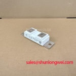
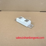
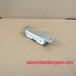
The confirmed product identifiers are MMF400Y040DK1B, MACMIC, and a module package. The practical assessment below separates component specifications from system-level design considerations so that procurement and maintenance teams can record the evidence needed for installation approval.
Compare the selected semiconductor fuse’s total clearing I²t with the diode’s permissible I²t under matching conditions. This is a Design Consideration, not a published withstand claim for this model. The comparison must account for fault voltage, prospective fault current, initial junction temperature, and the duration associated with the semiconductor rating. Pre-arcing I²t alone does not represent the complete energy let through during fuse operation.
Use the equipment manufacturer’s fuse coordination schedule to establish the approved fuse family and operating conditions. Where a new fuse is proposed, its total clearing characteristics and peak let-through current require assessment against the semiconductor limits and the assembly’s fault-current capability. A favorable I²t comparison does not, by itself, guarantee freedom from package rupture or other damage during a short circuit.
Trace each power terminal to the schematic before disturbing the buswork. Record the installed conductor arrangement, contact hardware, and tightening specification. Mounting fasteners and electrical terminals can have different torque requirements; neither should inherit a value from another module merely because the hardware appears similar. Use the applicable assembly instructions and calibrated tooling when restoring connections.
Thermal condition also belongs in the protection review. Blocked airflow, degraded thermal interface material, or uneven mounting contact can raise the starting junction temperature before a fault occurs. Maintenance intervals should follow the equipment service plan and observed contamination rather than an invented module-specific calendar.
Maintenance Note: Trend terminal temperature rise under comparable load conditions and inspect heatsink airflow before returning the assembly to service.
MMF400Y040DK1B Operational Boundaries: Evaluating Diode Peak Reverse-Recovery Current and Limits
Evaluate reverse-recovery current using the manufacturer’s stated forward current, commutation rate, reverse voltage, and junction temperature. As a Design Consideration, peak reverse-recovery current and recovery time describe different aspects of commutation; recovery time alone does not establish recovery softness. The current waveform and associated voltage overshoot provide the relevant integration evidence.
During an approved switching assessment, use suitable voltage and current probes with controlled measurement-loop geometry. Separate genuine circuit ringing from probe-induced artifacts before changing the assembly. Reduce unnecessary commutation-loop inductance to limit overshoot, then validate the resulting voltage stress and damping with the actual circuit. Snubber selection belongs to that system assessment, not to a generic component-page prescription.
The following comparison is a documentation checklist, not an equivalence statement. In particular, the linked reference part should not be treated as a same-rating or drop-in replacement.
| Assessment item | MMF400Y040DK1B | GD300HFX170C6S reference |
|---|---|---|
| Manufacturer | MACMIC | Consult manufacturer datasheet |
| Product classification | Diode module | Verify device type and topology |
| Voltage and current ratings | Consult manufacturer datasheet | Consult manufacturer datasheet |
| Surge and recovery characteristics | Check ratings and test conditions | Compare only under matching conditions |
| Mechanical compatibility | Check terminal map and outline drawing | Check independently before substitution |
Engineers reviewing GD300HFX170C6S alongside this module should establish device function before comparing electrical limits. The IGBT design and operation essentials reference provides context for adjacent controlled switches; gate-drive and desaturation settings are not diode-module specifications. The Mitsubishi Electric diode module lineup offers general product-category context, not MACMIC rating evidence.
MMF400Y040DK1B Operational Boundaries: Evaluating Coordination of Primary Spark Gaps, MOVs, and Limits
Coordinate upstream surge arresters, MOVs, and local suppression by comparing their protective voltage levels with the stresses reaching the semiconductor terminals. The relevant surge-immunity reference is IEC 61000-4-5, not IEEE 61000-4-5. Test levels, coupling arrangements, and acceptance criteria belong to the equipment’s applicable requirements; they do not establish standalone module compliance.
As a Design Consideration, arrester coordination should address connecting-lead inductance, residual voltage, energy sharing, and protective-device behavior after overstress. RC suppression requires evaluation against repetitive circuit operation as well as surge events. General semiconductor context is available from Shindengen Power Semiconductors & ICs, without implying approval of this MACMIC component.
When evaluating compatibility with a grid-tied static var compensator or thyristor-switched capacitor assembly, designers should verify the module’s circuit role, blocking requirements, and protection coordination against the equipment documentation. Use the Field Engineer’s Handbook as a supplementary maintenance reference when documenting abnormal stresses. After damp storage or temperature transitions, assess condensation and contamination before energization, following the equipment’s approved inspection and drying procedures.