
Content last revised on October 28, 2026
Benchtop Waveform Tuning: Mitigating Switching Stress on MMG200Q120B6TC
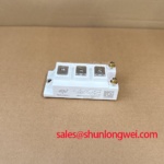
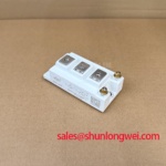
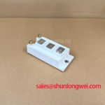
I compare gate voltage, collector voltage and switching current on the same acquisition before changing the external gate resistors around an MMG200Q120B6TC. On a legacy driver board, replacing the power module without reviewing its gate drive can leave an apparently functional repair with excessive switching stress. The practical objective is a repeatable waveform across the intended operating conditions, rather than the fastest achievable switching edge.
Design Consideration: Where the driver provides separate turn-on and turn-off paths, evaluate their resistors independently. Increasing turn-on resistance generally slows current commutation and can reduce ringing, but it also affects switching energy. Turn-off resistance influences the balance between voltage overshoot and turn-off loss. Component selection should follow measured behavior with the actual driver, interconnects and load; a resistor copied from another module is not a validated setting for this MacMic device.
Use appropriately rated differential probes and a suitable current probe, keeping measurement connections short and accounting for channel timing differences. Measure gate voltage relative to the emitter reference used by the driver. If ringing changes significantly when the probe arrangement changes, investigate the measurement setup before modifying the circuit. Record bus voltage, load current and thermal condition alongside each capture so that resistor comparisons remain meaningful.
Design Consideration: Reduce commutation-loop inductance through compact current paths and closely coupled outgoing and return conductors where the assembly permits. A laminated busbar can support that objective, but its effectiveness depends on the complete connection geometry. Maintain electrical clearances appropriate to the equipment insulation design rather than reducing spacing simply to shorten a conductor. Verify turn-off peaks at the module terminals, not only at a remote DC-link connection.
During compatibility assessment for electric material handling equipment or forklift low-voltage traction, compare the existing power-stage topology, driver interface, cooling arrangement and regenerative operating conditions before considering this module. Where a braking chopper and resistor absorb regenerated energy, inspect their operating coordination separately from the traction switching waveform. A rising DC link during deceleration can have several causes, including the braking command, resistor circuit or energy-management strategy.
Replacement comparisons should remain document-led. The F3L300R07PE4 provides another device reference for a maintenance comparison, not an established interchangeable replacement. Check topology, terminal mapping, mechanical fit and switching requirements before treating any alternative as a repair candidate.
Assembly Integrity & Layout Architecture: Fuse Arc-Voltage Coordination for MMG200Q120B6TC
Compare the semiconductor fuse’s total clearing characteristics with the fault conditions at its installation point before approving the protection arrangement around the MMG200Q120B6TC. Fuse current rating alone does not establish semiconductor protection. Prospective fault current, DC-link capacitance, circuit inductance, operating voltage and the fuse’s DC interruption capability all affect the outcome.
Design Consideration: Total clearing I²t describes the current-squared time integral through the fuse during interruption, including its arcing interval. It must not be treated as directly interchangeable with an IGBT’s short-circuit safe operating area. Compare I²t with a device withstand characteristic only where the manufacturer supplies an applicable limit and test conditions. A fast fuse can limit the consequences of a fault without necessarily preserving the semiconductor itself.
Check the fuse manufacturer’s peak arc-voltage information against the surrounding circuit. During interruption, the voltage across the fuse can exceed the normal supply voltage, and its distribution depends on circuit connections and stray inductance. Review the entire interruption path, including capacitor connections, conductors and protective devices. Neither rapid clearing nor a nominal fuse designation independently establishes protection against module enclosure damage.
For an existing assembly, inspect fuse holders and power connections for heat discoloration, disturbed contact surfaces and evidence of movement. Tightening should follow the applicable terminal and fastener instructions using a calibrated tool. Distinguish power-terminal requirements from baseplate mounting requirements; they are not automatically the same. Keep thermal-interface inspection and replacement within the equipment maintenance procedure, with the interval informed by thermal trends, service conditions and shutdown access.
Maintenance Note: Trend connection temperatures and check heatsink airflow during scheduled maintenance, with the equipment isolated before cleaning or tightening. After cold storage or a substantial ambient-temperature change, inspect for condensation before energization and follow the equipment’s environmental recovery procedure.
Packaging terminology should not be used to infer this module’s internal construction. Background references on sintering and flip-chip packaging describe general manufacturing concepts; neither establishes the die attachment or interconnection technology inside the MMG200Q120B6TC. Assembly decisions should remain tied to its documented external interfaces.
Transient Dynamics & Electrical Design: SCSOA and Overcurrent Protection for MMG200Q120B6TC
Trace the complete fault-response path from current rise or desaturation detection to gate discharge before assessing short-circuit protection. Include sensing delay, filtering, isolation propagation, driver response and current decay. A generic microsecond target is not a substitute for the module’s specified short-circuit withstand conditions.
Design Consideration: A type-I event involves turn-on into an existing short circuit; a type-II event develops while the device is already conducting. Their detection waveforms can differ, so review both where relevant to the equipment topology. Desaturation blanking must accommodate normal switching behavior without concealing a developing fault for an excessive interval. Validate the timing through the actual protection chain rather than relying solely on controller software timestamps.
Two-stage soft turn-off is a possible driver strategy, not a confirmed MMG200Q120B6TC feature. Where supported, a controlled initial gate discharge can moderate current fall before the driver completes turn-off. Excessively slow discharge can increase fault energy, while abrupt interruption can increase inductive overshoot. The system designer should establish the discharge profile against applicable device limits using controlled testing and suitable fault containment.
Inspect the isolation channel when switching transitions coincide with unexplained protection trips or gate disturbances. Common-mode transient immunity is a property of the selected isolator or driver under stated conditions, not a blanket guarantee for the assembled board. Probe the driver input, isolated output and gate waveform to distinguish command corruption, supply disturbance and local gate coupling. Keep gate-drive return routing separate from high-current paths where the architecture permits.
For a parallel power stage, do not assume that a positive temperature coefficient guarantees current sharing. Static sharing depends on the relevant operating region and device characteristics; dynamic sharing also depends on gate-path symmetry, power connections and thermal balance. Review each branch rather than accepting a satisfactory total-current trace as sufficient evidence.
The FF300R12ME4_B11 is another power-module reference when reviewing separate switching positions within a converter; its inclusion does not establish electrical compatibility or a rectifier function. Broader Industrial Applications context can support the equipment review, while the repair record should retain the actual gate-drive settings, protection timing captures, terminal checks and thermal observations for the installed MMG200Q120B6TC.