

Content last revised on September 29, 2026
MSD200-16 Circuit Protection and Post-Surge Reverse Voltage
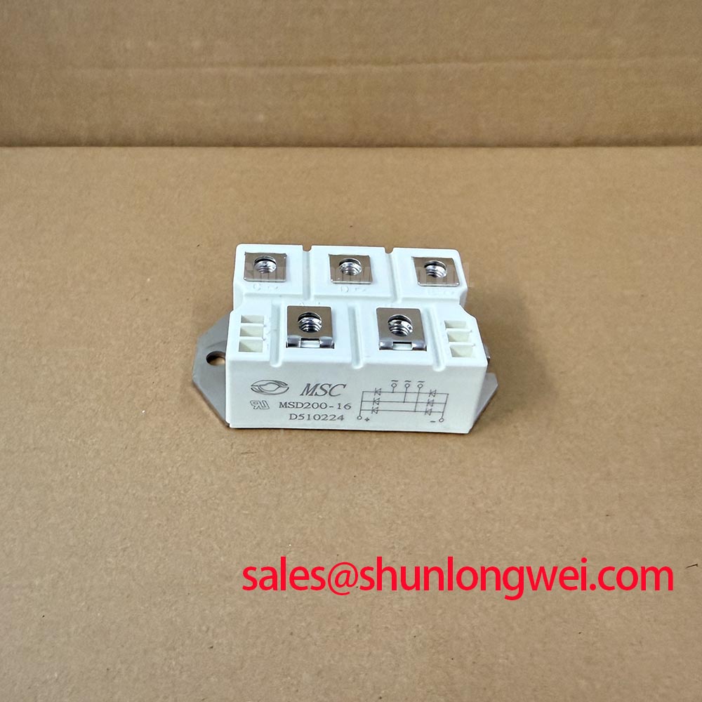
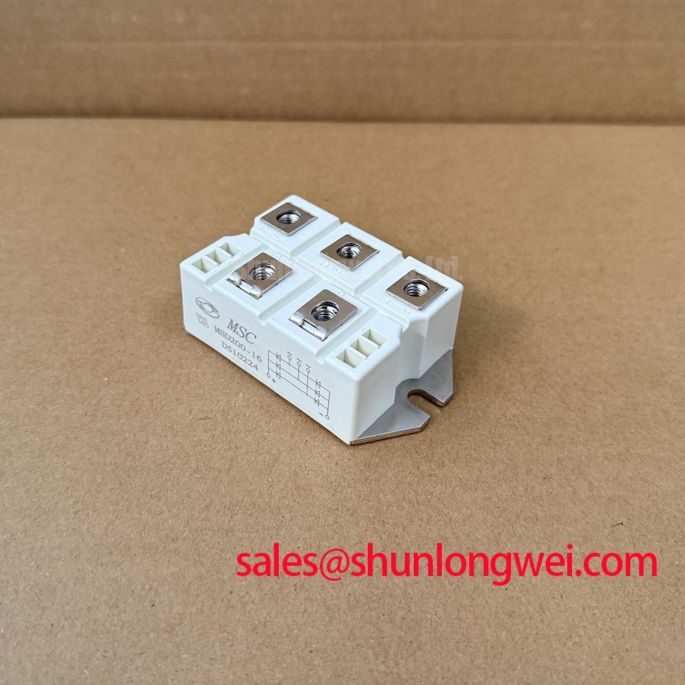
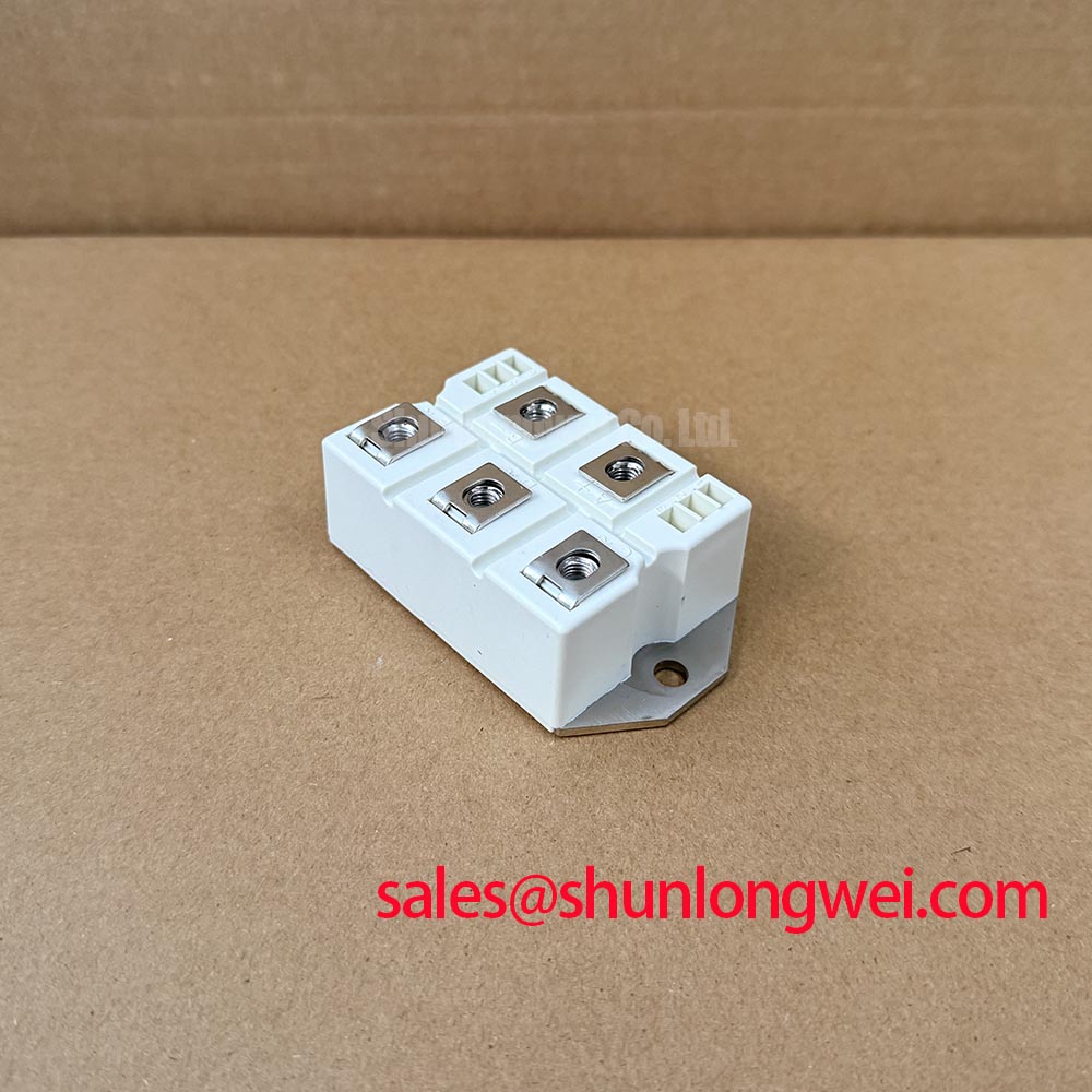
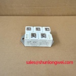
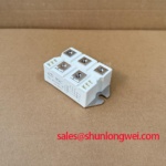
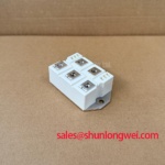
MSD200-16 | Manufacturer identification: Microsemi | Category: Thyristor/Diode Module | Package: Module | Published voltage and current ratings: not provided in the supplied specifications.
Measure the voltage across the power terminals after isolating the circuit and recording a surge event, then compare the result with the equipment schematic and a known-good phase. A normal-looking static measurement does not establish that the module can safely withstand reverse voltage immediately after a surge. That assessment depends on the applicable surge-current rating, the starting junction temperature, the pulse shape and the recovery conditions.
For MSD200-16, no numerical surge rating, junction-temperature limit or reverse-voltage rating is available in the supplied specifications. An engineer evaluating a high-voltage three-phase motor solid-state soft starter should obtain those limits from the applicable factory datasheet before coordinating the semiconductor fuse. Compare the fuse clearing data with the module’s specified surge and I²t limits at the relevant operating condition; do not infer protection from the fuse’s continuous-current marking. As a Design Consideration, inspect the associated MOV network for its connection to the affected phase and capture the voltage at the module terminals during a controlled test. The equipment designer must determine whether the measured transient remains within the verified module limits.
Field Diagnostics and MSD200-16 Thermal Contact
Check the heatsink imprint and mounting contact pattern when a serviced phase runs hotter than its peers under comparable load. Patchy thermal compound transfer, debris or uneven clamping can impair heat flow without producing an obvious electrical fault. Inspect the module seating surface and the heatsink together; a clean electrical test alone cannot establish sound thermal contact.
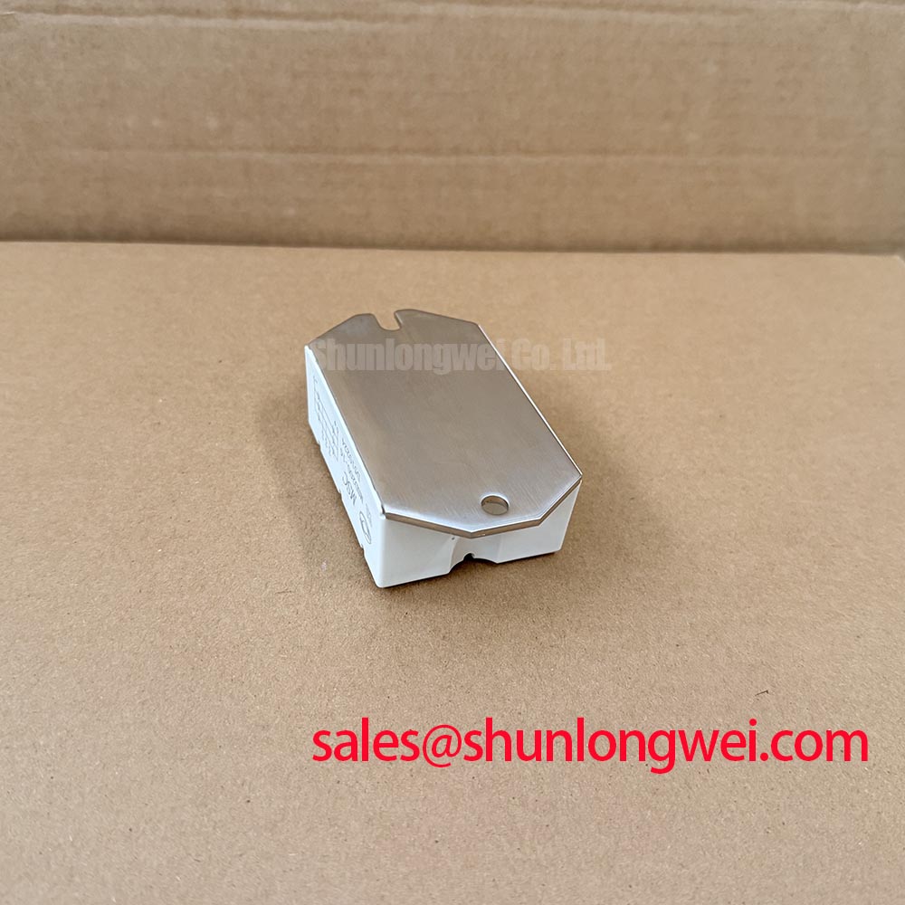
The supplied specifications identify a module package but provide no baseplate material, mounting torque, thermal resistance or transient thermal impedance value. Consequently, junction-temperature margin during a starting pulse cannot be calculated reliably from the supplied information. As a Design Consideration, use the approved mounting instructions for the exact module and compare measured case or mounting-surface temperature with the equipment’s established test record. Transient thermal impedance matters because a brief starting event heats the junction differently from steady operation; the system engineer should assess the actual pulse sequence against verified thermal data rather than extrapolate from continuous load alone.
Bench reminder: Isolate and discharge the power circuit before disturbing module terminals or heatsink hardware. During replacement assessment, compare terminal positions, mechanical seating and the complete electrical ratings of any proposed alternative. A listing for PD2008 can be reviewed as a separate candidate, but its presence in the same sourcing workflow does not establish drop-in compatibility.
Preventing Spurious Faults During MSD200-16 Commutation
Capture current and terminal-voltage waveforms through the faulting commutation interval, rather than attributing every trip to the power module. A recovery-current peak, circuit inductance or an upstream switching event can each affect the observed transient. If the documented circuit path includes a freewheeling diode, its reverse-recovery behavior is relevant to current overlap and switching loss; reverse recovery in diodes explains the underlying mechanism. Neither diode presence nor recovery ratings for MSD200-16 are established by the supplied specifications.
As a Design Consideration, keep the commutation path compact to limit inductive overshoot, then verify peak stress at the actual operating conditions. Avoid assigning an EMI compliance claim to the module: emissions depend on the assembled equipment, its wiring and its control strategy. In a soft-starter repair, compare phase-to-phase waveforms and inspect snubber and MOV connections before changing gate-control settings.
If the equipment also contains a separate rectification stage, MCC200-14IO1 is a component to examine against that stage’s schematic and ratings, not an assumed companion connection to MSD200-16. For broader inverter-topology context while tracing recurring power-stage faults, see Peak Efficiency in Solar and Energy Storage; its topology discussion does not define this module’s internal circuit.
MSD200-16 Gate Trigger Checks and Assembly Layout
Probe the gate-to-reference waveform at the module connection when one phase fires inconsistently. Compare its pulse shape and timing with a healthy phase under the same operating condition, and inspect the return path for shared impedance or loose terminations. A gate pulse visible at the controller output may differ from the pulse delivered at the module terminals.
The supplied specifications do not state a gate-current requirement, pulse-rise limit, holding-current characteristic or internal terminal map for MSD200-16. Those values should not be assigned from its model number or from a generic thyristor circuit. As an Engineering Recommendation, trace each control and power terminal against the equipment drawing and the applicable module documentation before energizing the assembly. Where the documented device requires repeated firing pulses, verify their delivery throughout the intended conduction interval; where it does not, avoid imposing that strategy.
Pro Tip: Keep the gate feed and its reference return close together to reduce coupled switching noise, then confirm the delivered trigger waveform at the module terminals during controlled commissioning. Check mounting pressure and terminal security after assembly using the exact hardware instructions, rather than borrowing a torque value from another module package.