
Content last revised on September 23, 2026
Benchtop Waveform Tuning: Mitigating Stress via Thermal Duty Cycle Management of Bypass Co on MCC200-14IO1
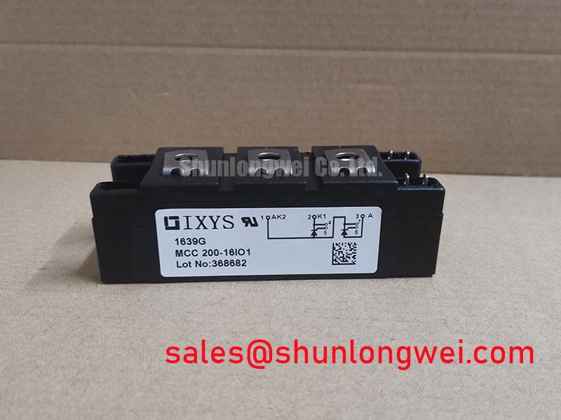
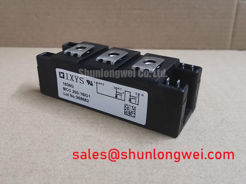
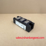
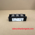
With the cabinet isolated and discharged, first compare the installed module marking with the replacement label, inspect the module housing for cracks or terminal damage, and check for unintended shorts or abnormal cold-state resistance between the relevant power, gate, and cathode terminals against the original circuit documentation. MCC200-14IO1 is an IXYS dual thyristor module with a specified voltage rating of 1400 V and specified current rating of 200 A, supplied in a module package. These ratings identify the electrical boundary of the component, but the installer should verify the original controller topology, terminal assignment, fuse coordination, heatsink condition, and trigger board behavior before energizing a repaired starter.
| Parameter | Official Specification |
|---|---|
| Manufacturer | IXYS |
| Module model | MCC200-14IO1 |
| Product category | Dual thyristor module |
| Specified voltage rating | 1400 V |
| Specified current rating | 200 A |
| Package | Module |
In a high voltage three phase motor solid state soft starter, a dual thyristor module is typically evaluated as part of the phase control path that gradually applies motor voltage during acceleration. The bypass contactor, sometimes identified as Co in controller drawings, normally takes over only after the motor reaches the intended running condition. Before replacing a failed module, trace the existing phase path from the incoming supply, through protection components and the thyristor assembly, to the motor output. This confirms whether the MCC200-14IO1 occupies a phase control position compatible with the original wiring arrangement.
Motor locked rotor current can be several times the motor nameplate current, and phase angle control is commonly used to reduce the electrical and mechanical stress associated with starting. A target such as reducing a locked rotor event from six to eight times rated motor current toward a substantially lower controlled current is a system control objective, not an official rating of the MCC200-14IO1. The soft starter controller, motor load, supply impedance, programmed ramp, and bypass sequence determine the actual current waveform. The 1400 V and 200 A specified ratings must be assessed against measured line conditions and the original equipment documentation.
Thermal duty assessment should begin with recorded start frequency, measured acceleration duration, motor current capture, and heatsink temperature trend. A starter that works during a short unloaded trial can still accumulate excessive heat during repeated starts or under a high inertia load. Design Consideration: use the original manufacturer documentation for thermal impedance data, allowable junction conditions, and mounting requirements rather than applying figures from another thyristor family. The supplied official parameter set does not establish a fuse I²t value, thermal resistance value, terminal torque, or permitted overload profile for this exact module.
Fast semiconductor fuse coordination is also a system protection task. Inspect the existing fuse type, fuse holder contact condition, conductor size, and evidence of heat around the line side terminals. The fuse must be coordinated using the original starter design information and the applicable module documentation so that a downstream fault does not rely solely on the thyristor structure to interrupt energy. Do not transfer an I²t selection from a different current class simply because its package appears similar.
⚠️ Field Alert: Isolate and verify discharge before removing gate leads, then reinstall every power connection and thermal interface exactly as required by the equipment documentation because loose terminals or uneven mounting pressure can create localized heating.
MCC200-14IO1 Operational Boundaries: Commutation Turn-Off Voltage Stress Limits
Commutation behavior should be checked at the waveform level rather than inferred from an ordinary multimeter reading. In an AC soft starter, the outgoing thyristor naturally transfers current as the supply polarity changes, yet cable inductance, motor characteristics, snubber condition, and line disturbances can alter voltage transition behavior. The MCC200-14IO1 specified voltage rating is 1400 V; it does not by itself define the allowable overshoot, reverse recovery current, recovery time, or electromagnetic compatibility behavior of the completed starter.
When the starter has a history of nuisance firing, blown protection devices, or abnormal waveform ringing, inspect the RC suppression network, MOV condition, gate lead routing, and controller reference connection before installing another module. A degraded snubber capacitor, damaged resistor, or incorrect wire return can change the voltage seen across the module during commutation. Design Consideration: minimize parasitic loop inductance where practical to reduce inductive voltage excursion, then verify peak device voltage with properly rated differential measurement equipment during controlled switching tests.
The supplied official specifications do not state reverse recovery peak current or soft recovery time for MCC200-14IO1. These values should not be estimated from the module’s current class. Engineers assessing commutation stress should obtain the applicable IXYS documentation for this part and compare it with oscilloscope captures from the original starter circuit. Probe placement matters: a long ground connection can introduce apparent ringing that is not present at the device terminals.
For context, modern power conversion equipment may use different semiconductor technologies and module architectures. Wolfspeed Silicon Carbide power modules illustrate that switching behavior depends strongly on the semiconductor technology and package design. That information must not be treated as a specification for this silicon dual thyristor module. Likewise, ceramic substrate materials such as silicon nitride are discussed in the wider power module industry, but no internal substrate material should be assumed for MCC200-14IO1 without the relevant manufacturer documentation.
For a broader practical reference when separating device rating checks from system transient measurements, consult The Ultimate IGBT Knowledge Base. The testing principles concerning loop layout, transient capture, and thermal assessment can support bench discipline, while the final evaluation must remain specific to the thyristor module and its original starter circuit.
MCC200-14IO1 Thermal Electrical Optimization: Turn On Current Rise Limiting and Practical Tuning
A replacement module should not be used to conceal an unresolved turn on problem. Before energization, check whether the original RC snubber components remain electrically connected across the intended terminals, whether MOV devices show signs of physical distress, and whether the gate driver board has clean isolation spacing and intact connector retention. The purpose of the suppression network is to control system generated voltage transitions and avoid unintended triggering under transient conditions. Its resistor and capacitor values are determined by the specific power circuit, wiring inductance, motor characteristics, and measured switching behavior.
Series reactors and saturable reactors are sometimes present in high current starter assemblies to shape current rise under specific operating conditions. Their suitability cannot be established from the MCC200-14IO1 voltage and current ratings alone. Engineering Recommendation: retain the original reactor arrangement during a repair unless the system designer has confirmed a revised design through waveform and temperature testing. Altering magnetic components, snubber parts, or MOV selection without confirming the resulting peak voltage and current can move stress from one part of the starter to another.
The heatsink deserves the same attention as the electrical path. Remove old interface residue carefully, check the mounting surface for debris or distortion, and inspect adjacent modules for uneven clamp marks. The required mounting hardware, screw specification, torque, thermal compound type, and layer thickness should be verified from the original equipment and applicable module documentation. These are mechanical integration requirements, not published values in the official parameters listed here.
After installation, begin with the safest available controlled commissioning condition permitted by the equipment procedure. Observe phase balance, trigger timing consistency, and the rise of heatsink temperature through the intended start sequence. If one phase behaves differently, verify gate pulse delivery, phase wiring, snubber continuity, and the load path before attributing the condition to the MCC200-14IO1 itself. A comparison with a known good phase can be useful when performed with appropriate isolation and measurement practice.
Where a repair requires a formal compatibility comparison, the SKKT 106B14E can be reviewed as another thyristor module listing. It should be treated as a separate item for engineering comparison only. Terminal layout, current capability, voltage classification, gate characteristics, thermal interface, and protection coordination must all be verified against the original MCC200-14IO1 installation before any substitution decision.
MCC200-14IO1 Operational Boundaries: Gate Trigger Current Dynamics and Limits
Gate circuit inspection is essential because a dual thyristor module depends on correct firing delivery from the starter controller. Confirm the original gate and cathode terminal references from the applicable wiring diagram before reconnecting leads. The supplied official data identifies the MCC200-14IO1 as a 1400 V, 200 A dual thyristor module, but it does not provide gate trigger current, gate pulse rise time, holding current, latching current, or repetitive pulse requirements. Those values must be taken from the correct IXYS technical documentation rather than assumed from another module.
Use an isolated measurement method appropriate to the gate driver design to compare firing pulses across phases. Look for missing pulses, distorted leading edges, inconsistent pulse trains, poor return paths, or pulses that disappear during a load transition. These observations may indicate a driver supply issue, optical isolation problem, connector fault, gate return routing issue, or controller timing condition. They do not establish a single cause without comparison to the circuit documentation and a known good waveform.
Multi pulse firing can be used in some soft starter control strategies to improve turn on reliability across changing load and line conditions. Whether it is appropriate depends on the original controller logic and the documented gate requirements of the installed module. Designers should verify gate pulse width, repetition behavior, isolation component capability, and common mode transient performance against the actual phase voltage waveform. Avoid extending or strengthening gate drive solely on the assumption that more gate energy is always beneficial.
During final troubleshooting, inspect the driver board for contamination, loose plug contacts, damaged isolation barriers, and heat affected passive components. Verify that each gate lead is routed as intended and that its return is not shared through an unintended high current path. This practical check often prevents misleading diagnosis after a module replacement, particularly where a repaired soft starter experiences intermittent firing loss only under real motor load.