


Content last revised on October 28, 2026
MT/D3-430-24-A2 Circuit Protection & Reliability: Calibrating Thermal Duty Cycle Management of Bypass Contactors
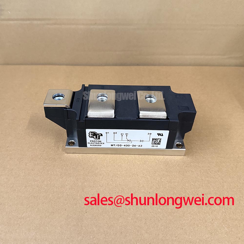
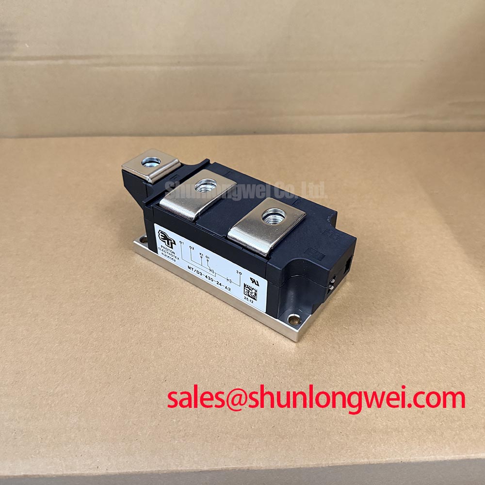
Isolate the power circuit, verify the absence of hazardous voltage, and disconnect parallel paths before checking resistance at the MT/D3-430-24-A2 power terminals. Compare readings with the equipment schematic and corresponding healthy branches; an in-circuit reading alone cannot establish semiconductor condition. Record the complete nameplate designation and terminal arrangement before removing the module so that replacement assessment preserves the original circuit connections.
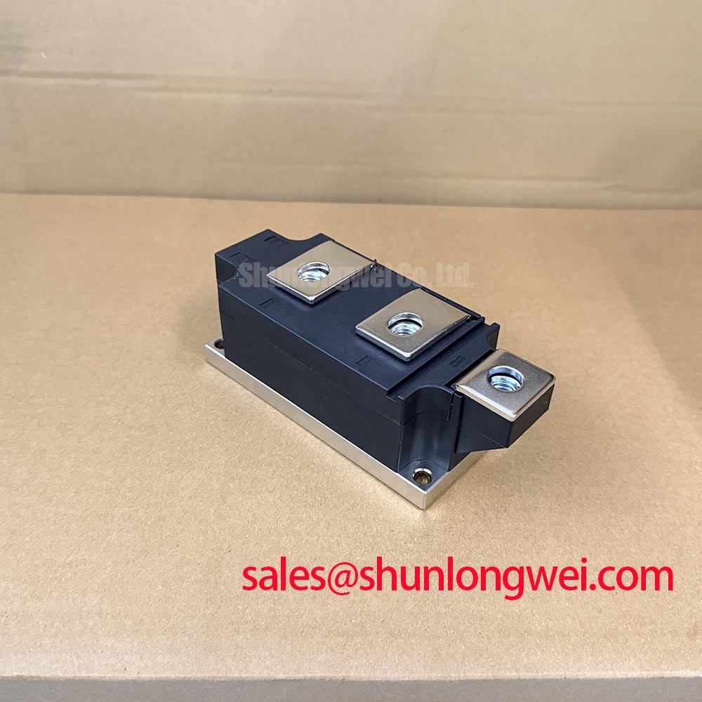
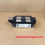
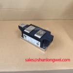
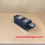
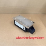
The SanRex (Sansha Electric) MT/D3-430-24-A2 is identified here as a thyristor / diode power module in a SanRex power-module housing. For procurement, match the complete designation rather than interpreting individual characters as voltage or current ratings.
Check bypass-contactor feedback against the controller’s firing command and measured branch current before increasing the permitted starting duty. As a Design Consideration, delayed bypass engagement can extend semiconductor conduction and heating, while an incorrectly sequenced transfer can disturb current sharing between the intended paths. Capture the transfer event rather than relying only on the contactor’s audible operation.
When evaluating compatibility with a high-voltage three-phase motor solid-state soft starter, designers should verify the module’s circuit configuration, blocking capability, surge limits, and triggering requirements against the equipment design. Phase-angle control changes the applied motor voltage, but achievable current reduction depends on motor loading and acceleration requirements. Reduced voltage also reduces available starting torque; a lower current setting does not automatically produce a successful start or eliminate mechanical shock.
For protection coordination, compare the semiconductor’s documented surge-current conditions and I²t withstand with the fuse manufacturer’s total-clearing data at the prospective fault current. This is an Engineering Recommendation, not a fuse selection derived from the model name. Include supply impedance, protective-device operating conditions, and the equipment manufacturer’s coordination requirements. A fuse’s continuous-current marking alone does not establish semiconductor protection.
Use the manufacturer’s SanRex Sansha Electric Power Semiconductor Modules resources when matching circuit symbols and device terminology. Preserve the distinction between repetitive operation, a specified surge event, and protective clearing; they describe different stresses.
Preventing Spurious Faults: Junction-to-Heatsink Heat Dissipation Guidelines for MT/D3-430-24-A2
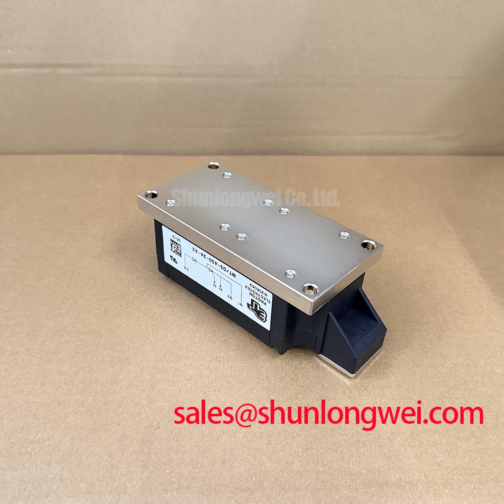
Inspect the heatsink mating surface and the removed module’s interface imprint before cleaning away the thermal compound. As a Design Consideration, uneven contact, contamination, or mechanical loading from misaligned busbars can impair heat transfer and complicate temperature-based fault assessment. Do not identify the baseplate material from appearance alone.
Separate junction-to-case thermal resistance from the mounting interface and heatsink-to-ambient path when reviewing thermal duty. The module’s documented thermal resistance describes a defined boundary, not the complete installed cooling arrangement. Compare temperature trends under repeatable operating conditions, including the starting interval and bypass transfer, rather than treating an accessible surface temperature as a direct junction-temperature measurement.
Field Alert: Follow the specified mounting sequence and torque, and align the busbars without using terminal screws to pull them into position.
Keep the PDMB 200E6 comparison at the qualification stage; a related product listing does not establish interchangeable electrical connections or mounting geometry. The following checks define the evidence needed for a replacement decision without assigning unsupported ratings.
| Comparison item | MT/D3-430-24-A2 | PDMB 200E6 |
|---|---|---|
| Voltage and current ratings | Consult model-specific datasheet | Consult model-specific datasheet |
| Circuit and terminal mapping | Match installed schematic and terminal markings | Check against the same circuit requirements |
| Mechanical compatibility | Record footprint, terminal positions, and clearances | Compare dimensional drawing before selection |
| Thermal and protection coordination | Review original operating and fault conditions | Revalidate against those conditions |
Field Diagnostics & Commissioning: RC Snubber Network Optimization in MT/D3-430-24-A2 Topologies
Measure the voltage transient across the relevant switching branch with appropriately rated differential instrumentation before changing the RC snubber. As a Design Consideration, distinguish an unwanted triggering event from a commanded firing pulse, connection intermittency, or measurement pickup. Correlate branch voltage, current, and trigger timing under the same operating event.
Snubber resistance and capacitance should be evaluated against the circuit’s transient behavior, component pulse loading, and semiconductor limits. Any series reactor requires the same system-level assessment: limiting current rise also changes circuit dynamics. Preserve the original protection network during initial diagnosis unless the equipment service procedure specifies otherwise.
Where a separate rectifier stage is present, assess devices such as MTC110A1800V within that stage’s own topology and protection requirements, not as an automatic substitute. The ROHM fast recovery diode resources provide related diode context; they do not establish this SanRex module’s recovery characteristics.
Use the Power Electronics Masterclass for broader troubleshooting context while retaining device-specific triggering criteria. Document the corrected connections, protection components, and measured switching behavior in the equipment service record before returning the assembly to operation.