

Content last revised on October 28, 2026
MTC180A1600V Circuit Protection & Reliability: AC-to-DC Transfer Characteristics
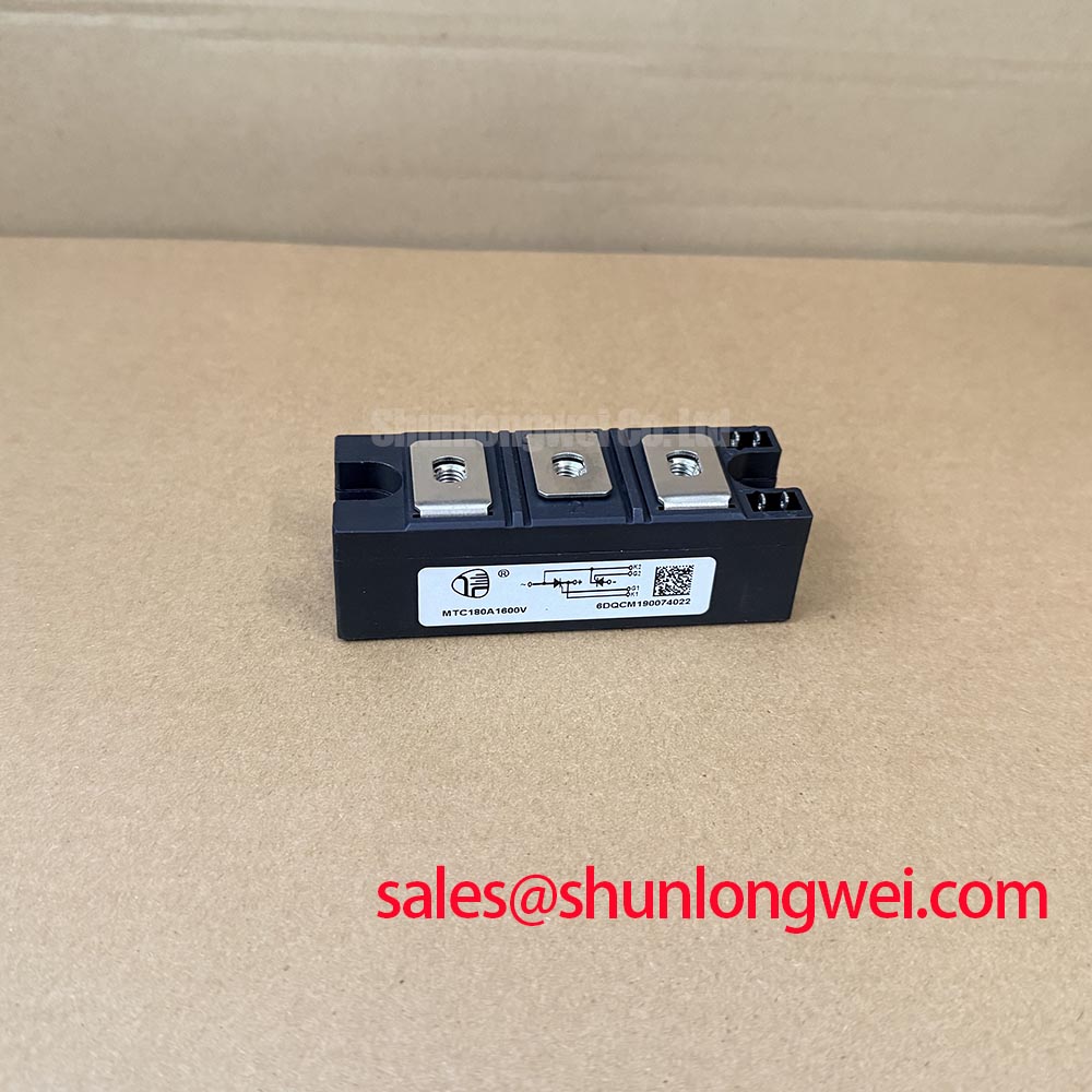
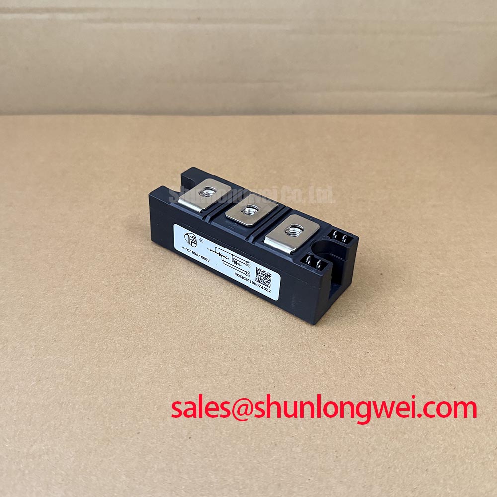
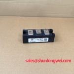
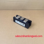
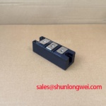
MTC180A1600V is identified as a SanRex (Sansha Electric) thyristor / diode module in a SanRex Power Module package. Incoming inspection should establish electrical identity and connection compatibility before any energized evaluation.
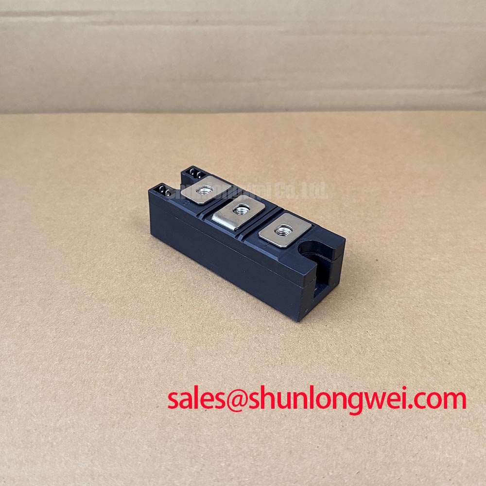
- Isolate the rectifier, verify that stored energy has discharged, and identify the module terminals from the equipment schematic before connecting a meter.
- Record cold terminal measurements with lead polarity, instrument range, and module temperature so comparisons remain repeatable.
- Inspect the mounting surface, terminal hardware, and insulating barriers for damage before reconnecting busbars.
- Match the firing-board connections to the documented power-circuit arrangement rather than inferring pin functions from terminal position.
| Product identification | Specification status |
|---|---|
| Model | MTC180A1600V |
| Manufacturer | SanRex (Sansha Electric) |
| Product category | Thyristor / Diode Module |
| Package description | SanRex Power Module |
| Blocking voltage, rated current, internal circuit, and dimensions | Consult the matching manufacturer datasheet; numerical ratings are not established by the supplied specification record. |
| Surge withstand, isolation test conditions, and mounting torque | Consult Datasheet |
Correlate the firing command with measured line voltage, load current, and average DC output before attributing an output discrepancy to the module. Design Consideration: phase-controlled conversion depends on bridge topology, current continuity, source impedance, and load behavior; firing angle alone does not define the transfer characteristic.
For an engineering evaluation spanning 0° to 150°, treat that interval as a proposed controller test range, not an official MTC180A1600V operating specification. Establish the permissible range from the converter design. In a fully controlled bridge with continuous current, increasing firing delay reduces average output and can enter inversion only when the surrounding circuit supports it. A partly controlled bridge behaves differently.
Measure input power factor with equipment that captures distorted current. Displacement between voltage and the fundamental current component is distinct from distortion-related power factor reduction. Reactive demand should therefore be assessed alongside current waveforms, rather than inferred from DC output alone.
For a potential high-current green hydrogen electrolyzer DC power rectifier, designers should evaluate compatibility against the existing bridge arrangement, firing system, cooling assembly, and load-control requirements. The manufacturer’s SanRex power semiconductor resources provide the appropriate reference point for matching device documentation.
MTC180A1600V Assembly Integrity & Layout Architecture
Trace the commutation path through the module terminals and adjacent conductors before altering the busbar arrangement. Design Consideration: minimizing unnecessary loop area can reduce inductive voltage excursions, but the acceptable layout must be established through system-level waveform measurements.
Diode reverse-recovery peak current and recovery time describe different aspects of commutation; neither independently establishes switching loss or recovery softness. Compare published characteristics only at matching current, temperature, reverse voltage, and current-change conditions. For thyristor operation, circuit-commutated turn-off requirements also matter; diode recovery time is not a substitute for thyristor turn-off time.
A handheld diode-range measurement can document polarity-dependent conduction, but it cannot establish rated blocking capability or switching recovery. An untriggered thyristor need not produce the forward indication expected from a diode. Compare readings with the documented circuit and an equivalent known-good assembly under the same measurement conditions.
💡 Bench Tip: With the assembly isolated and discharged, use ESD precautions and record meter polarity when comparing cold readings against a known-good module.
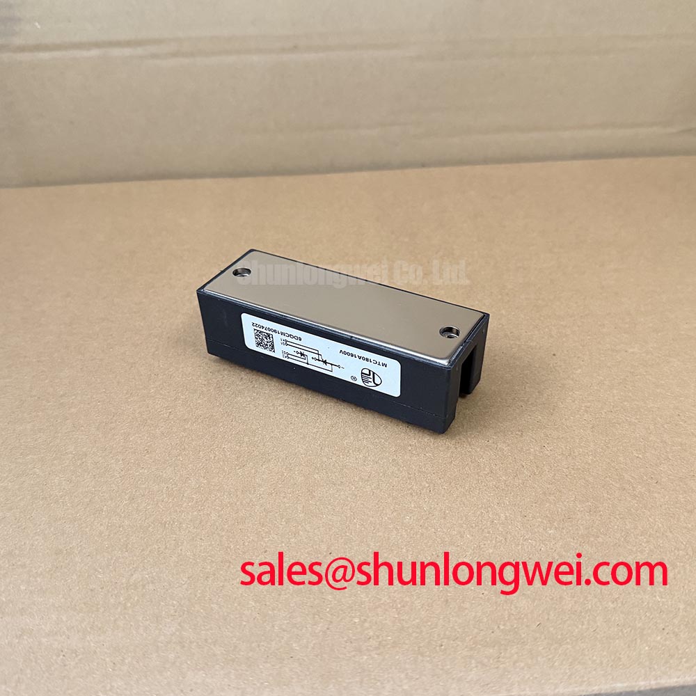
Check mounting flatness, terminal loading, and the specified tightening procedure before thermal testing. Assess terminal spacing and insulation against the equipment’s working-voltage and installation requirements; a baseplate dielectric test does not establish every system insulation margin. General passivation principles do not establish that this particular module uses glass-passivated chips.
MTC180A1600V Circuit Protection & Reliability: Type-2 Coordination and Short-Circuit Protection
Compare the semiconductor fuse’s total clearing I²t with the module’s applicable withstand data at compatible test conditions. Design Consideration: pre-arcing I²t alone excludes the arcing interval and is insufficient for a complete protection assessment. Include prospective fault current, applied voltage, initial temperature, and the protective device’s published operating limits.
Type-2 coordination is an equipment-level classification under the applicable assembly standard, not an automatic property of a fuse-module pairing. An I²t comparison cannot guarantee containment or freedom from damage during a short circuit. Protection evaluation also needs peak let-through current, fault-path impedance, and assembly-level verification.
IGBT desaturation detection, VCE(sat)-based thresholds, soft shutdown, and SCSOA must not be transferred directly to thyristor protection. Removing a conventional thyristor’s gate signal does not interrupt established conduction. Firing inhibition, fault interruption, and restart logic must follow the actual converter topology.
For replacement assessment, compare the PDMB 200E6 only through its own circuit diagram, ratings, terminal arrangement, and mechanical drawing; it is not established here as an interchangeable substitute. Where the equipment includes an operator display, The Ultimate Guide to Industrial TFT LCD Technology addresses that separate subsystem, not semiconductor protection limits.