


Content last revised on October 28, 2026
MTT160-12 Circuit Protection & Reliability: Minimizing Commutation Turn-Off Voltage Spikes
- Confirm the terminal arrangement against the original SVC or thyristor switched capacitor wiring diagram before energization.
- Inspect the mounting surface, heatsink contact, fastener condition, and thermal interface for even mechanical seating.
- Check the power path for correct fuse coordination and inspect the gate circuit insulation before applying control pulses.
- Record the module identification and compare the replacement ratings with the removed device.
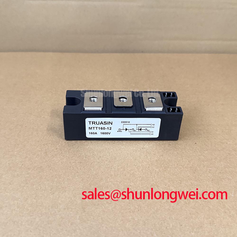
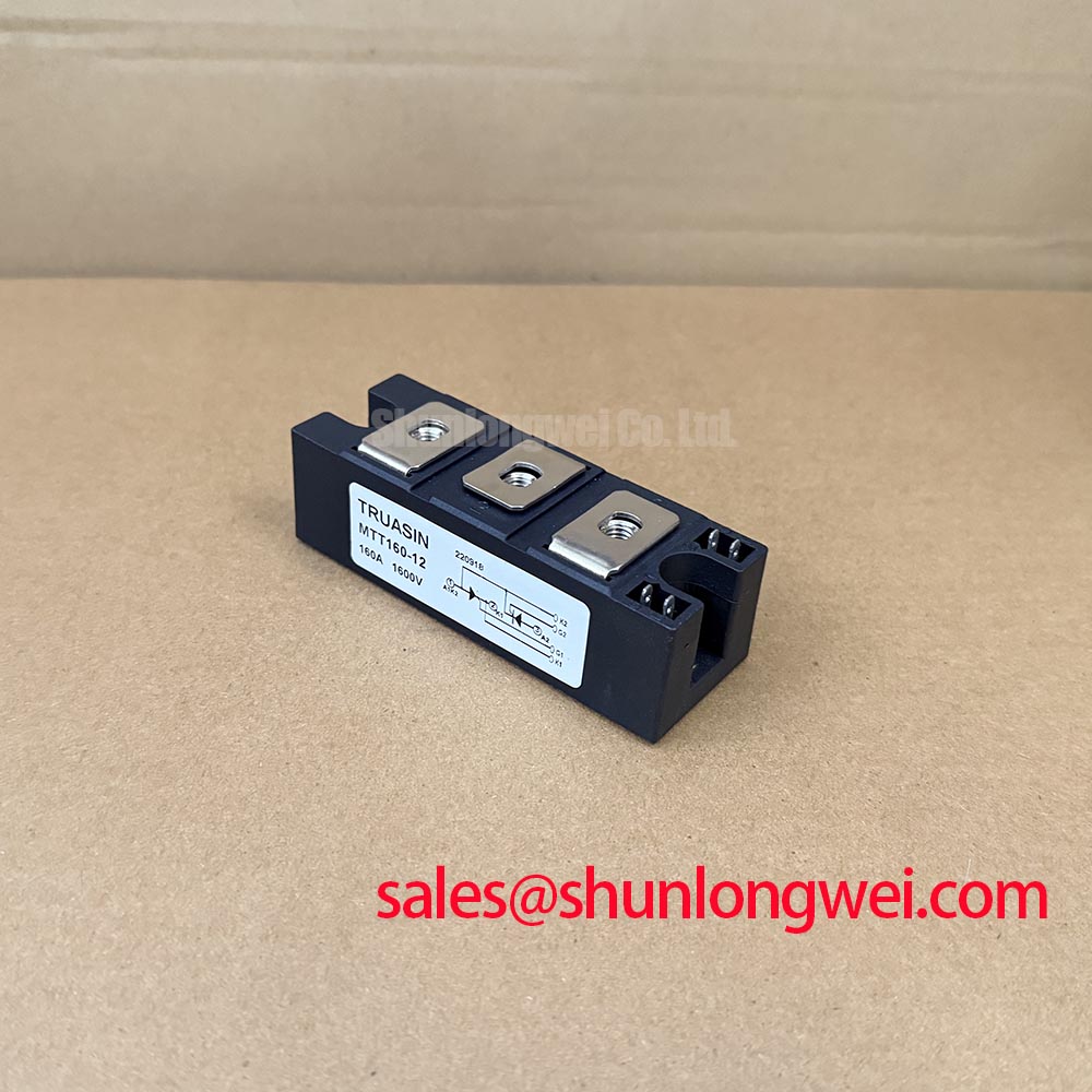
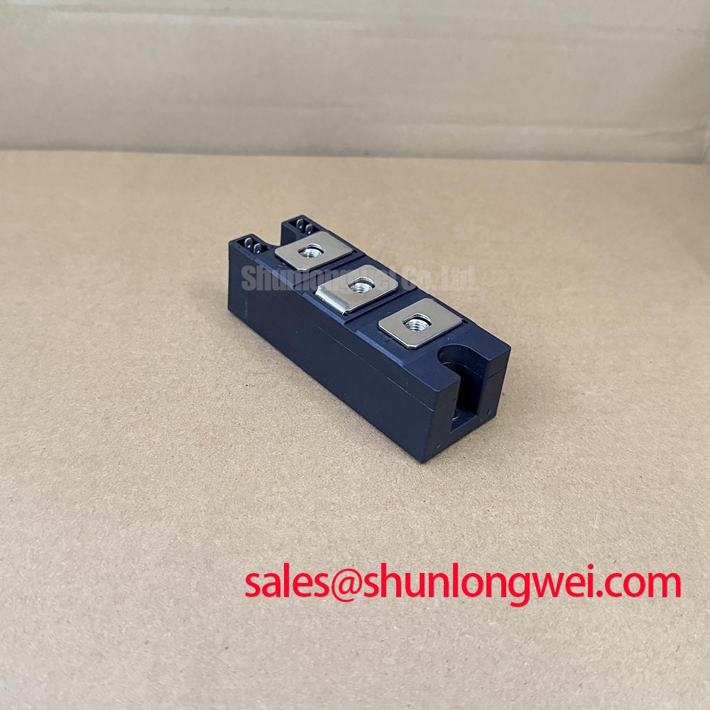
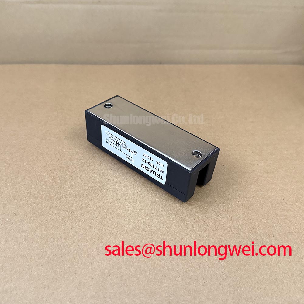
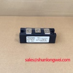
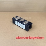
Use the cold terminal check and wiring inspection to establish a safe starting point before testing MTT160-12, a SanRex (Sansha Electric) thyristor power module used in industrial power conversion assemblies.
| Manufacturer | SanRex (Sansha Electric) |
| Part number | MTT160-12 |
| Voltage and current ratings | Verify against the original manufacturer datasheet, including the applicable rating conditions. |
| Housing | SanRex Power Module |
| Product category | Thyristor Module |
Protection coordination should begin with the commutation path, because reverse-recovery current and recovery time influence both switching loss and the voltage stress seen by the surrounding network. During a service inspection, review the fuse I²t coordination table together with the actual semiconductor protection arrangement rather than selecting a fuse from RMS load current alone. The fuse must interrupt the available fault energy in a way that is compatible with the module’s surge and thermal limits.
For a grid-tied static Var compensator or thyristor-switched capacitor bank, the technician should compare the measured commutation waveform with a known-good phase path. Excessive reverse-recovery current, uneven recovery between phases, or a sharp turn-off voltage excursion can point to a mismatch in gate timing, line impedance, or snubber condition. The thyristor recovery behavior should be evaluated with the complete commutation network in place, since the external reactor, busbar, and capacitor arrangement affect the observed result.
Terminal connections require low-resistance, mechanically stable contact. Clean mating surfaces, preserve the original conductor orientation, and follow the manufacturer’s specified mounting torque for the actual terminal hardware. Heatsink flatness and thermal interface coverage also matter because local contact pressure can create a hot region even when the average enclosure temperature appears acceptable.
SanRex power modules can be evaluated alongside other industrial switching assemblies, but electrical topology and gate-drive requirements must be matched rather than assumed. A neutral cross-reference point for procurement review is the PDMB 200E6, which should be assessed independently against the original circuit and mechanical interface.
Transient Dynamics & Electrical Design: Firing Timing and Commutation on MTT160-12
In a phase-controlled rectifier, changing the firing angle changes the average DC output, conduction interval, and reactive power demand. SVC operation depends on the branch topology: a thyristor-controlled reactor uses firing-angle control, whereas a thyristor-switched capacitor branch is normally switched in or out at a suitable point on the voltage waveform rather than continuously phase-controlled. Check the control system under the operating states appropriate to the installed branch.
Use isolated voltage and current probes to observe the line waveform, module conduction interval, and capacitor or reactor current. The important comparison is between the commanded gate timing and the actual main-terminal conduction. A delayed or uneven phase response may arise from gate pulse distribution, control synchronization, line imbalance, or an abnormal commutation path. The phase controller should also be reviewed for pulse width, isolation integrity, and repeatability under the intended switching sequence.
Confirm the voltage and current ratings and their applicable conditions in the original manufacturer datasheet. System engineers should match those ratings with the installed DC-link or AC line, fault level, cooling arrangement, and duty cycle before approving a replacement. The module rating by itself does not establish the permissible operating point of the complete converter.
In a larger power conversion chain, an upstream rectifier or complementary switching stage may influence the stress applied to the thyristor branch. The PK55GB40 may be reviewed as a separate associated module within an appropriate topology, while its voltage, current, isolation, and control requirements remain subject to its own documentation.
MTT160-12 Operational Boundaries: Evaluating the RC Snubber Network
RC snubber evaluation should focus on suppressing unwanted voltage rise and preventing false turn-on during rapid commutation. Select the resistor and capacitor as a system network, then inspect the resulting voltage across the main terminals and the gate-to-cathode control path during the most demanding switching condition. The correct values depend on circuit inductance, operating voltage, switching sequence, and the permitted leakage or standby current of the assembly.
A saturable reactor can also affect the initial current slope and the distribution of stress between parallel or sequential branches. Its behavior should be evaluated while monitoring current sharing, capacitor charging, and thermal response. Localized heating at a terminal or busbar may indicate an installation or current-sharing issue, but it should be confirmed through temperature measurement and connection inspection rather than assigned to the module alone.
💡 Pro Tip: Keep the commutation and gate-drive loops physically compact and symmetrical, then verify peak voltage, current sharing, and gate immunity with controlled switching tests before returning the equipment to service.
Thermal design should account for the full path from semiconductor junction through the case to the heatsink and enclosure airflow. Heatsink selection, interface material, airflow, and mounting pressure remain system-level design considerations. The technical guide The Advanced Thermal Management Revolution provides broader context for thermal interface and cooling architecture.
For comparison with wider power-semiconductor practice, engineers may consult Shindengen Power Semiconductor Modules & Diodes. External reference material can support design review, but final protection, insulation, EMC, and thermal validation must be performed on the completed equipment.