

Content last revised on October 3, 2026
PD064VT2 Identification and Replacement Checks
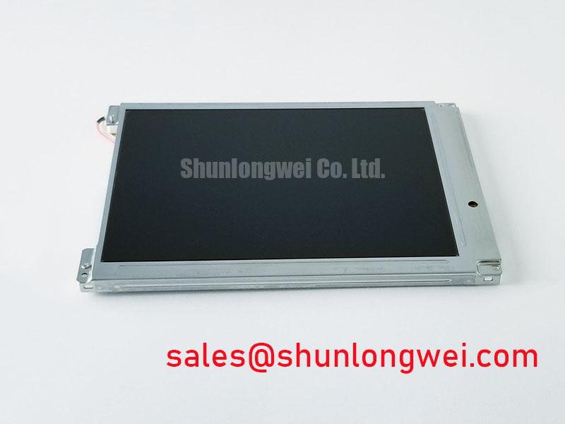
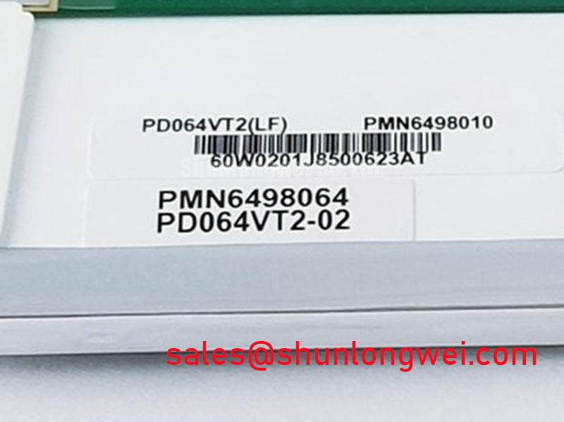
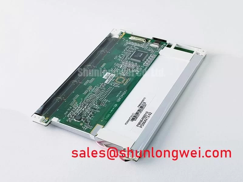
Begin the replacement check by isolating the display assembly, inspecting the connector and bezel for physical damage, and confirming the nameplate against PD064VT2 before applying power. The supplied factory context identifies this unit as a PVI (Prime View International) industrial grade LCD/HMI panel in a TFT LCD display module format. It should therefore be evaluated as a complete display interface component, with electrical, optical, mechanical, and cable compatibility verified against the original equipment documentation.
For repair engineers working on automated guided vehicles, forklift telematics terminals, and industrial HMI equipment, the most important first decision is whether the replacement preserves the host system’s interface conditions. The available official product context confirms the model identity and product category, but it does not publish a complete pinout, supply voltage, active area, resolution, luminance rating, backlight type, timing table, touch technology, or operating temperature range. Those values should be taken from the original panel documentation or the equipment manufacturer’s service record rather than inferred from the model name.
| Verified product information | Available value |
|---|---|
| Model | PD064VT2 |
| Manufacturer | PVI (Prime View International) |
| Product category | Industrial Grade LCD/HMI Panel |
| Module construction | TFT LCD Display Module |
Single Vertical Hairline Defect & Sub-Pixel Column Driver Open-Circuit Localization
When a narrow vertical line appears on the image, begin with a controlled visual inspection rather than pressing the panel surface or flexing the frame. Record whether the line remains fixed during a full-screen white image, a full-screen black image, and primary-color test screens. Red, green, and blue fields can help establish whether the abnormality follows a column, a sub-pixel group, or the image data path. This is a diagnostic method, not a factory acceptance threshold for PD064VT2.
A 45-degree flashlight inspection can add useful information when the display is unpowered. A dark shadow, lifted edge, cracked polarizer surface, or localized reflection may point toward an external optical or mechanical issue. If the visible line changes with backlight state but not with image content, inspect the illumination path and connector seating. If it remains aligned to the same image column during different source patterns, the engineer should compare the panel-side connector, cable continuity, and the known-good signal path before attributing the symptom to an internal driver connection.
Do not assume that a vertical hairline proves a specific chip-on-glass or column-driver failure. The same appearance can be influenced by connector contact, source timing, cable strain, frame pressure, or damage elsewhere in the display assembly. A microscope inspection of the accessible connector area, followed by continuity checks with the panel disconnected, is more defensible than a resistance value invented for field diagnosis. The supply must remain isolated during ohmmeter measurements, and the equipment service procedure should define any permitted test points.
The supplied factory information does not include a PD064VT2 fuse rating, fuse I2t coordination table, terminal map, mounting torque, or connector pin assignment. These items must be verified from the original panel drawing or host equipment documentation. Applying an assumed supply voltage or reversing an unconfirmed connector can damage the module even when the mechanical outline appears compatible. The system integrator should verify the required supply voltage from the original panel documentation.
For a replacement assessment, document the defect location, connector condition, cable routing, display pattern, and host controller output. An oscilloscope may be used on the approved system-side test points to compare a failed unit with a known-good signal path, but probing should follow the equipment manufacturer’s grounding and access instructions. The purpose is to distinguish an input-data problem from a panel-side image defect without making a single-cause diagnosis from appearance alone.
Constant Luminance Output Control & L70/B50 Backlight Reliability Verification
The supplied official context does not identify the backlight technology used by PD064VT2, nor does it publish a luminance value, LED current, L70 rating, B50 distribution, half-life, or MTBF figure. Those values must not be assigned to this model by analogy with another industrial display. A repair engineer should first inspect the original backlight driver, its output connector, and the equipment’s brightness control method. The panel documentation should then be checked for the permitted current, enable logic, dimming interface, and power sequencing.
Constant luminance evaluation should be performed with a repeatable test image and stable ambient conditions. Check the center and edge areas for visible nonuniformity, then compare the result after the unit has reached a stable operating condition. A localized bright or dark region may involve the optical stack, backlight path, cable connection, pressure from the bezel, or driver behavior. Without a published optical specification for PD064VT2, these observations are useful for comparison with a known-good assembly but are not proof of a particular internal material or failure mechanism.
Where the enclosure uses narrow side rails, a thermal design review may be appropriate. The mechanical team can assess whether the frame, spreader, or mounting bracket creates a concentrated heat path near the display edge. This is a Design Consideration, not an official PD064VT2 thermal requirement. Any change must preserve the panel’s flatness, avoid local pressure, and maintain clearance from the connector and flexible cable. The actual thermal limit should come from the panel specification and the complete equipment validation plan.
L70 and B50 are reliability metrics that require an identifiable test method, operating condition, sample definition, and source. No such values are included in the supplied PD064VT2 factory data. Engineers should request the applicable original documentation when service life is a purchasing requirement. A reseller should not convert a general backlight expectation into a model-specific lifetime promise.
For practical service work, compare brightness control behavior at the host connector before replacing the complete panel. Confirm that the controller’s enable signal, dimming command, and supply behavior match the original design. If the system uses a separate constant-current driver, the driver’s protection state should be checked under the manufacturer’s prescribed procedure. If the panel incorporates its own backlight electronics, the connector definition and power sequence still require confirmation. The Ultimate Guide to Industrial TFT LCD Technology provides additional background for structured industrial display evaluation.
💡 Pro Tip: Disconnect power before inserting or removing the display cable, and verify the connector orientation from the equipment drawing rather than relying on visual symmetry.
Eye-Diagram Voltage Margin & Differential Noise Floor Verification in High-Vibration Bays
PD064VT2 should not be described as having a confirmed LVDS or TTL interface unless the original panel documentation identifies that interface. The supplied factory context confirms the display category but does not provide the signal standard, data mapping, pixel clock, lane count, pinout, termination, or timing limits. During replacement planning, inspect the controller board marking and cable assembly, then obtain the panel timing table before selecting test equipment or defining a signal-integrity limit.
If the host uses a differential display link, the engineering team may evaluate eye opening, common-mode behavior, and differential noise at the approved measurement location. A commonly encountered differential interconnect target is 100 ohms, but this is a Design Consideration for the complete signal path, not a confirmed PD064VT2 specification. The cable, connector, board launch, receiver, and probe setup all influence the result. The system designer should verify the actual impedance requirement from the controller and display documentation.
In a high-vibration equipment bay, cable retention is as important as electrical screening. Inspect the cable bend radius, clamp position, connector latch, shield termination, and clearance from switching power components. A cable that moves against a sharp bracket can create intermittent behavior that resembles timing instability. Compare the display signal with a known-good unit while monitoring the system’s power rails and control signals. If a horizontal band or pixel disturbance appears near a variable-frequency drive, check the complete grounding and cable-routing arrangement before adding a ferrite or changing the panel.
A 360-degree shield termination may be considered when the cable construction and enclosure bonding support it, but it should not be imposed as a model-specific requirement. Common-mode ferrite components can alter the signal path and must be evaluated for compatibility with the actual data rate and edge behavior. These are system-level EMC measures. PD064VT2 itself cannot be represented as independently passing an equipment-level CISPR or EN 55011 test.
JEIDA and VESA mappings should also be treated as separate compatibility checks. A display can show an image with incorrect color ordering, swapped channel arrangement, or timing interpretation while appearing electrically active. Confirm the mapping in the original documentation and compare color bars, grayscale steps, and text edges. If the host documentation is unavailable, record the observed behavior but avoid presenting an unverified mapping as an official feature of PD064VT2.
Optical Luminance Degradation Curve & CCFL-to-LED Modernization Retrofit Pathways
The supplied official information does not confirm whether PD064VT2 uses CCFL, LED, or another backlight arrangement. It also provides no cold-ignition voltage, PWM dimming ratio, acoustic-noise limit, optical degradation curve, or MTBF value. A retrofit decision must therefore begin with physical identification of the original backlight assembly and its connector, followed by review of the host power architecture. The system integrator should verify the required supply voltage and backlight control method from the original panel documentation.
A CCFL-based assembly normally requires its designated inverter and high-voltage insulation arrangement, while an LED retrofit requires a compatible constant-current driver and an appropriate enable or dimming interface. These are different electrical subsystems. Substituting one for the other without confirming current regulation, connector allocation, startup behavior, insulation spacing, and mechanical clearance can produce an apparently illuminated panel that does not meet the equipment’s safety or optical requirements.
Do not assign the often-quoted 1500 to 1650 Vrms ignition range, a 1000:1 PWM ratio, or a greater-than-50,000-hour lifetime to PD064VT2 because those figures were not supplied as official specifications for this model. If such values are required for an engineering change, they must come from the original backlight documentation, the proposed driver manufacturer, or a qualified validation report. Any reliability claim should identify its test conditions and measurement definition.
For a modernization assessment, measure the available enclosure opening, bezel overlap, connector position, cable exit direction, and mounting-hole relationship. The replacement must sit without bending the glass or pressing the active area. Anti-glare or anti-reflective surface treatment should also be verified from the panel documentation or by direct comparison, since glare performance depends on the viewing environment, cover window, lighting, and surface condition. The same caution applies to glove operation, wet-touch behavior, and resistive or capacitive touch compatibility: none is confirmed by the supplied PD064VT2 product data.
In AGV and forklift telematics applications, designers may evaluate the panel for a rugged HMI or monitoring enclosure, subject to vibration, sealing, sunlight, connector retention, and thermal validation. The appropriate decision depends on the complete display assembly and host controller, not on the model number alone. Before release, verify the electrical interface, optical behavior, mechanical fit, backlight control, and display timing against the original equipment records and the documented acceptance procedure.