
Content last revised on September 17, 2026
Transient Dynamics & Electrical Design: RC Snubber Network Optimization for PDT400N16
| MPN | PDT400N16 |
|---|---|
| Manufacturer | SanRex (Sansha Electric) |
| Category | Diode Module |
| Topology | Three Phase Bridge / Dual Diode |
| Package | SanRex Power Module |
| Series | Standard |
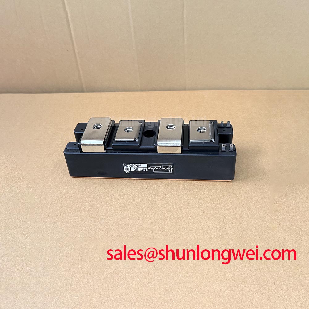
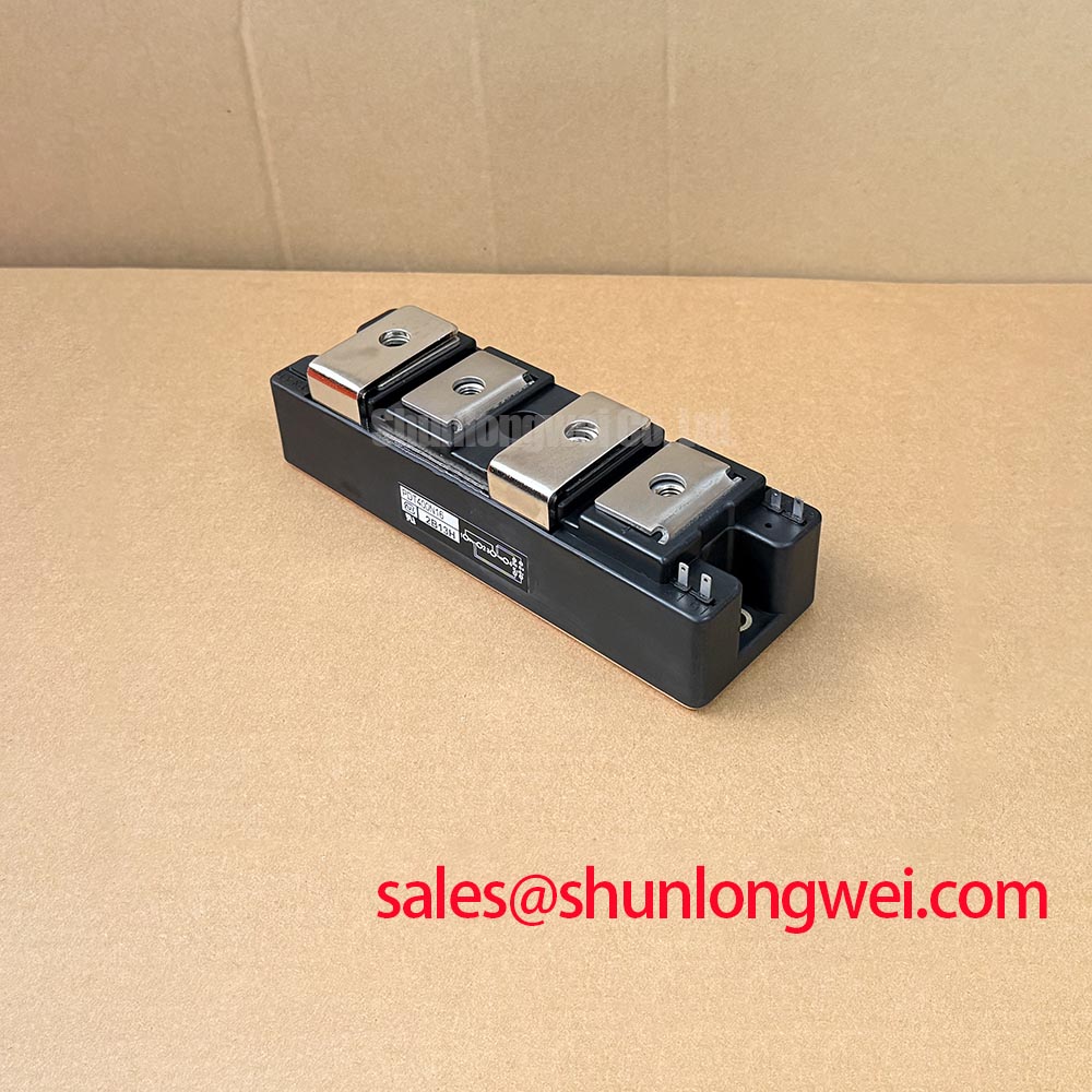
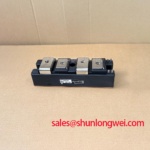
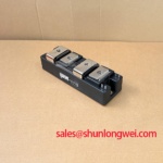
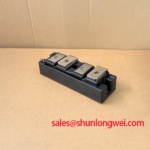
Probe the device terminals and the DC bus with an isolated differential measurement setup while the converter operates at reduced controlled power, then compare transient ringing during each commutation event. The PDT400N16 is a SanRex three phase bridge / dual diode power module; its actual terminal identification must follow the equipment schematic and the module connection drawing rather than terminal position assumptions.
RC snubber evaluation is an Engineering Recommendation based on measured voltage overshoot, ringing frequency, and commutation behavior. Place the snubber loop physically close to the commutating path so that busbar and lead inductance do not dominate the damping network. A series saturable reactor can also be evaluated where the existing induction heating power supply topology requires controlled current rise, but its suitability depends on measured current slope, thermal behavior, and the control sequence of the complete converter.
Check terminal hardware for discoloration, looseness, and uneven contact pressure before altering the snubber arrangement. Creepage and clearance around the live terminals must remain consistent with the original equipment insulation arrangement, especially where conductive dust, moisture, or furnace residue can accumulate. 💡 Pro Tip: Keep positive and negative high current bus paths closely coupled and symmetrical to reduce turn-off overshoot, then confirm the resulting margin through suitable commutation or transient testing.
SanRex power semiconductor product information can be referenced through SanRex power semiconductor modules when matching the device family to the original equipment documentation. For an installed rectifier assembly, inspect the associated auxiliary rectification stage as well; PD10M440H is a separately listed power module that can be assessed against its own electrical and mechanical requirements.
Preventing Spurious Faults: Reverse Recovery Charge Guidelines for PDT400N16
Capture the current waveform through the commutating diode path and inspect the reversal interval for excessive recovery current, abrupt current collapse, or repeated ringing at the point where the next phase assumes conduction. Reverse recovery behavior affects switching loss and conducted or radiated interference, yet no reverse recovery charge, peak recovery current, recovery time, or softness value is stated in the supplied official specification for PDT400N16.
This absence means those values must not be assigned to the module from generic diode families. As a Design Consideration, compare the waveform against a known stable converter channel under identical probe placement and operating conditions. A sharp recovery transition can interact with transformer leakage inductance, busbar geometry, and converter timing. It may indicate that the commutation loop, suppression network, control synchronization, or load condition requires examination rather than proving a single component fault.
Where the topology includes inductive control loads, a flyback path limits the voltage generated when current is interrupted. The underlying principle is described in this technical reference on flyback diode protection. In a three phase converter, however, the relevant path must be verified against the actual bridge diagram because freewheel, commutation, and auxiliary clamp functions are not interchangeable.
For repair material review, FRS300CA50 can be evaluated as a separately specified device only after checking topology, terminal arrangement, voltage class, current class, thermal interface, and control requirements against the original assembly. It should not be treated as a drop-in replacement without that verification.
PDT400N16 Operational Boundaries: Evaluating Fuse Total Clearing I2t versus Device Melt Limits
Read the installed semiconductor fuse marking, trace its protected branch, and obtain the fuse manufacturer’s pre-arcing and total-clearing I2t curves before energizing a repaired converter. The official supplied data for PDT400N16 identifies the product category, topology, package, and standard series, but does not provide device surge current, I2t withstand, junction temperature, or fuse coordination values.
Fuse coordination is therefore a Design Consideration, not an official rating claim for this module. The protection study should compare the fault current available from the source, the fuse clearing behavior at that prospective current, conductor and busbar capability, and the withstand limits documented for the exact installed semiconductor device. This work is important for dead-short conditions, where a fuse selected only by continuous current rating may not clear quickly enough to limit mechanical and thermal damage.
Inspect fuse clips, bolted joints, and busbar contact faces for heating evidence. Replace damaged insulation barriers and maintain the original terminal separation. Thermal contact between the module base and heatsink also needs a clean, flat interface and controlled fastening according to the original module documentation. Practical guidance on heat removal and assembly constraints is available in The Advanced Thermal Management Revolution.
Field Diagnostics & Commissioning: Three-Phase Rectifier Output Evaluation for PDT400N16 Topologies
Measure the three-phase line references and rectified output simultaneously to confirm phase balance, commutation behavior, and output stability. In an uncontrolled three-phase diode bridge, the average output is determined by the supply waveform, transformer arrangement, source impedance, and load behavior rather than by a firing-angle command. If a separate controlled converter stage is present in the equipment, evaluate its firing control independently from the PDT400N16 diode module.
Check the power connections and any associated control or monitoring circuits for secure termination and adequate isolation from the power circuit. Gate trigger current and gate trigger voltage are not applicable to the diode module itself. Any control thresholds used elsewhere in the converter must come from the original equipment documentation or the applicable SanRex datasheet.
For medium frequency induction melting and hardening furnace power systems, monitor output stability through the full permitted operating sequence while observing DC ripple, phase symmetry, cooling response, and abnormal acoustic or electrical noise. An irregular output trace may arise from supply imbalance, commutation conditions, load changes, suppression components, connection resistance, or a separate control stage. Isolate each possibility through measurement instead of assigning the symptom to a single cause.