
Content last revised on September 28, 2026
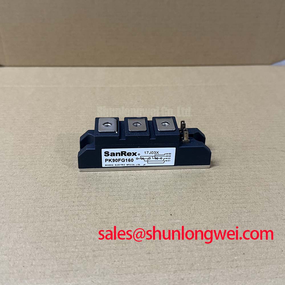
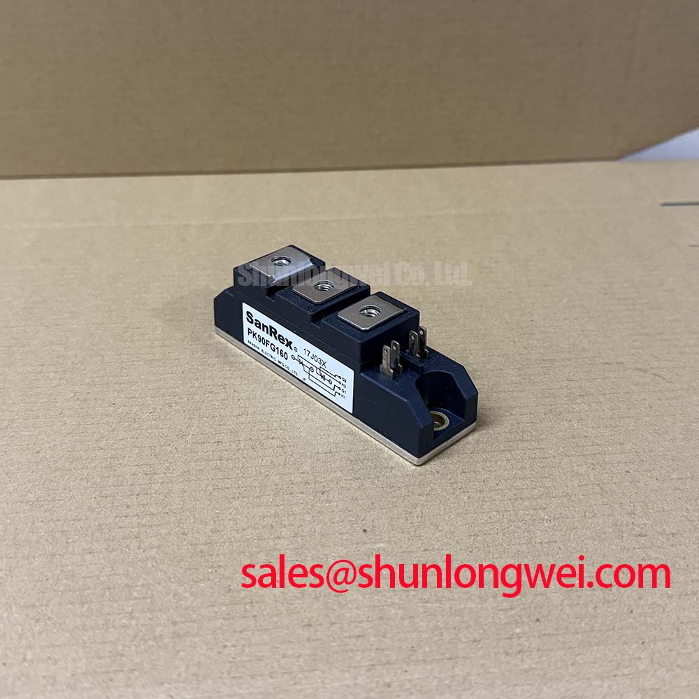
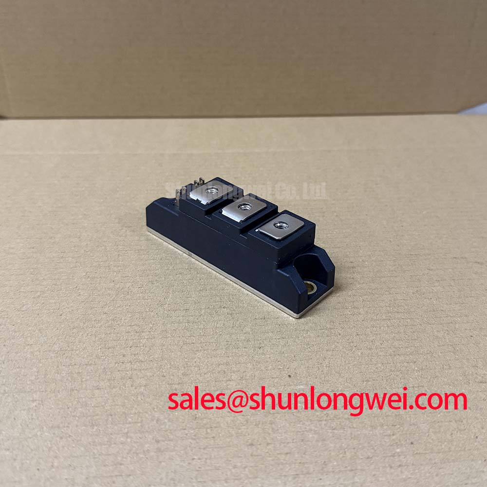
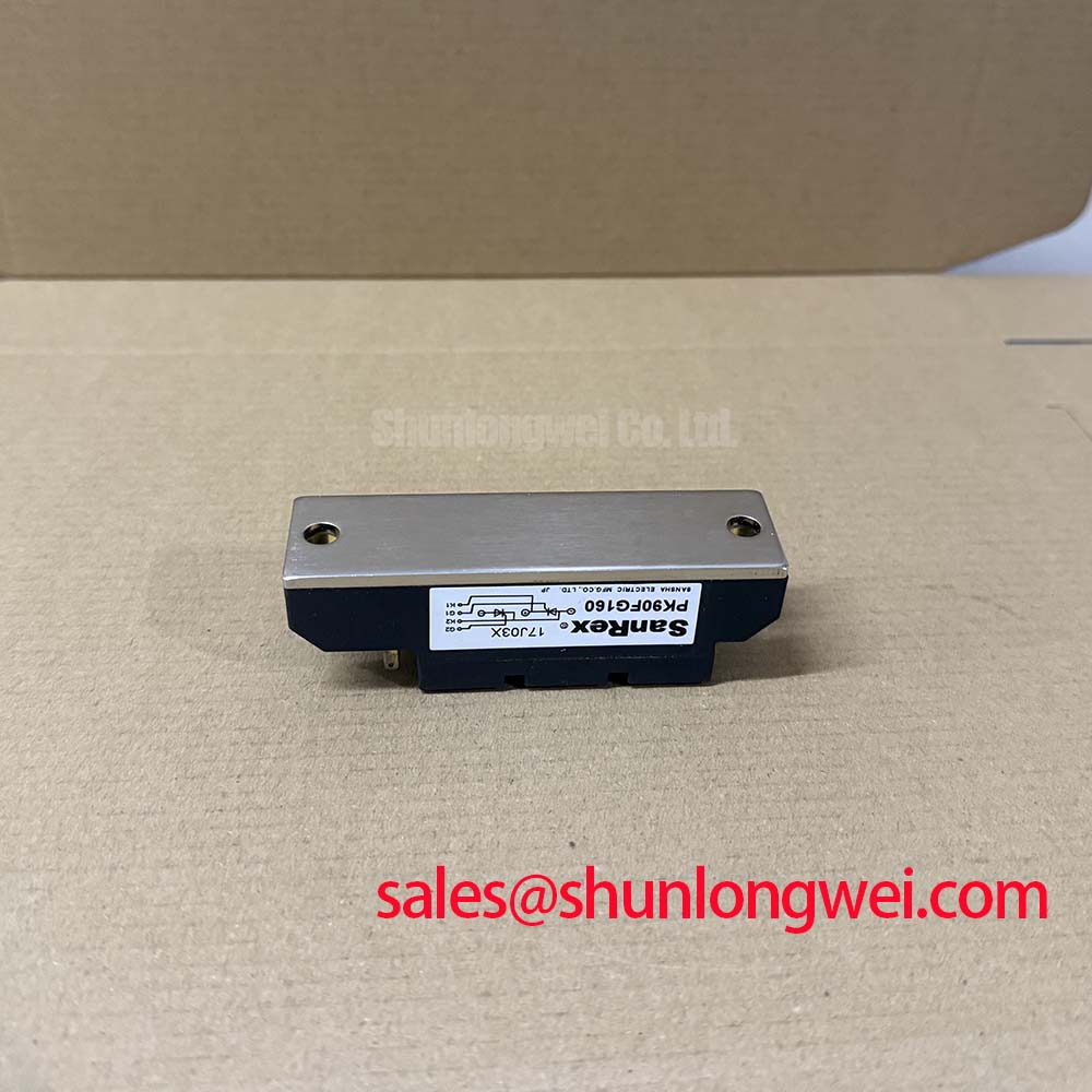
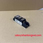
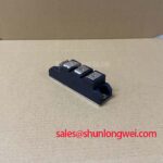
PK90FG160 SanRex 1600V 90A Thyristor Diode Module
Start the bench check with the equipment isolated, then confirm the nameplate and measure the module terminals against the original circuit documentation before applying gate or power connections. The PK90FG160 from SanRex (Sansha Electric) is specified as an Isolated Power Module with a rated voltage of 1600.0 V and a rated current of 90.0 A. These are official product specifications supplied for this model; gate timing, diode recovery values, fuse coordination data, terminal layout, dimensions, and mounting torque must be verified against the applicable manufacturer documentation before installation.
| Manufacturer | SanRex (Sansha Electric) |
| Model | PK90FG160 |
| Product category | Thyristor / Diode Module |
| Rated voltage | 1600.0 V Official Specification |
| Rated current | 90.0 A Official Specification |
| Package | Isolated Power Module Official Specification |
For a medium frequency induction melting or metal hardening power supply, the electrical rating is only one part of the replacement assessment. Engineers should compare the original circuit topology, terminal markings, trigger arrangement, cooling path, protection network, and mechanical envelope. The SanRex Sansha Electric Power Semiconductor Modules reference is the appropriate manufacturer-level source for device family information, while the specific installation should be validated against the original equipment documentation.
PK90FG160 Circuit Protection & Reliability: High-di/dt Gate Firing and Pulse-Train Timing
Before commissioning, inspect the module body, base surface, terminal hardware, and surrounding insulation for contamination or mechanical damage. A cold-state resistance check can help identify an obvious abnormal condition, but a meter reading alone cannot establish switching integrity or prove that the gate circuit is healthy. Compare the measured terminal relationships with a known-good unit or the approved circuit diagram, keeping the device disconnected from the energized power stage.
The supplied official data confirms the 1600.0 V voltage rating and 90.0 A current rating, but it does not provide a verified gate pulse rise-time limit, holding-current requirement, multi-pulse timing table, or gate di/dt specification. Those values should not be inferred from the model number. When evaluating a firing circuit, the service engineer should observe the gate-to-cathode waveform and the main-current response with suitable isolated measurement equipment. Pulse-train timing, back-porch current, dead time, and trigger synchronization remain system-level parameters that require validation under the actual transformer, load, and commutation conditions.
Semiconductor protection also depends on coordination between the fast fuse and the module. The fuse I2t value, prospective fault current, clearing time, and the module’s permitted surge-current data must be taken from matched manufacturer tables. The supplied product parameters do not include an I2t coordination table or surge-current limit, so a replacement decision should remain conditional until those values are confirmed. A related device such as PD25016A may be reviewed as a separate technical reference, but substitution requires dimensional, electrical, trigger, and protection verification by the system engineer.
⚠️ Field Alert: Disconnect all power and stored energy before removing terminals or gate wiring, and use the original equipment documentation to confirm terminal identity rather than relying on physical position alone.
Transient Dynamics & Electrical Design: RC Snubber Network Optimization for PK90FG160
In an induction heating converter, an RC snubber and any series saturable reactor form part of the complete commutation network rather than a fixed accessory of the module. The correct network depends on stray inductance, operating frequency, transformer leakage, load current, wiring length, and the measured switching waveform. Designers should minimize the high-current commutation loop and verify voltage overshoot at the module terminals during turn-on and turn-off tests.
The available official parameter set for PK90FG160 does not state a recommended snubber resistance, capacitance, pulse power rating, or saturable-reactor characteristic. These values therefore require calculation and bench validation from the actual circuit. A practical test sequence is to confirm the probe connection, observe the terminal voltage without changing the protection network, then compare the waveform after each controlled adjustment. The objective is to suppress excessive dv/dt and inductive overshoot without creating unacceptable snubber loss or additional commutation stress.
Long motor or transformer cables can behave as transmission paths, allowing reflected-wave effects to increase the voltage seen at the semiconductor terminals. Cable routing, termination, source impedance, and filter placement should be reviewed together. An oscilloscope measurement at the module bus is more useful than a control-board waveform alone because the local terminal voltage determines the actual electrical stress. The 1600.0 V rating is an official maximum rating reference, not permission to operate beyond the system’s verified transient margin.
Field Diagnostics & Commissioning: Diode Peak Reverse-Recovery Current and Softness in PK90FG160 Topologies
When the module is used in a topology containing a freewheel or commutation diode path, inspect the current transfer at the same time as the switching voltage. Reverse-recovery peak current and recovery softness can influence turn-off loss, ringing, and radiated interference, but the supplied data does not publish Irrm, trr, a softness factor S, or a recovery waveform for this model. These characteristics must be obtained from the applicable SanRex documentation or measured under defined test conditions; they should not be assigned from the 90.0 A current rating.
During commissioning, use a controlled load and compare current and voltage traces at the module terminals. Look for abnormal overlap between current and voltage, repeated ringing, or a recovery event that changes significantly with cable routing and temperature. Such observations may indicate a commutation, snubber, layout, measurement, or device compatibility issue, so the diagnosis should be confirmed by repeating the test with a known-good signal path and equivalent operating conditions.
The same review should cover the cooling interface. The isolated module package must sit flat against a clean heatsink, with the thermal interface material applied according to the equipment service specification. The supplied product information does not state a thermal resistance, transient thermal impedance network, maximum junction temperature, or mounting torque. Engineers should verify those values before setting a mechanical procedure. The resulting junction-temperature margin must be checked against the actual pulse profile rather than estimated from the package name alone.
Field Diagnostics & Commissioning: Power Factor Degradation and Harmonic Mitigation in PK90FG160 Topologies
For an AC to DC stage used in an induction melting or hardening supply, record input voltage, line current, firing command, DC-link behavior, and protective trips together. Firing angle changes can alter real power, reactive demand, harmonic current, and commutation margin. The supplied PK90FG160 specifications identify the voltage and current ratings, but they do not define a firing-angle transfer curve, power-factor value, harmonic limit, or permitted operating envelope across a control range.
System designers should therefore derive the expected converter behavior from the actual phase configuration and validate it with power-quality instrumentation. If harmonic mitigation is required, the choice of line reactor, passive filter, active compensation, or control adjustment belongs to the complete power system. The filter must be checked for resonance, thermal loading, fault behavior, and interaction with the induction load. The separate PD104VT2T1 reference may be relevant when reviewing associated rectifier or supply-stage hardware, but it is not a prescriptive replacement for the PK90FG160.
For broader switching-device context, the Wide Bandgap Revolution technical reference can support comparisons of switching behavior and layout priorities. It does not change the official ratings of this silicon module. Before returning a repaired furnace to service, verify terminal connections, insulation condition, protection coordination, cooling contact, gate waveform, and measured transient voltage under the intended operating sequence.