

Content last revised on September 22, 2026
Preventing Spurious Faults: ITSM Safety Derating and Repetitive Current Guidelines for MCD200-18IO1
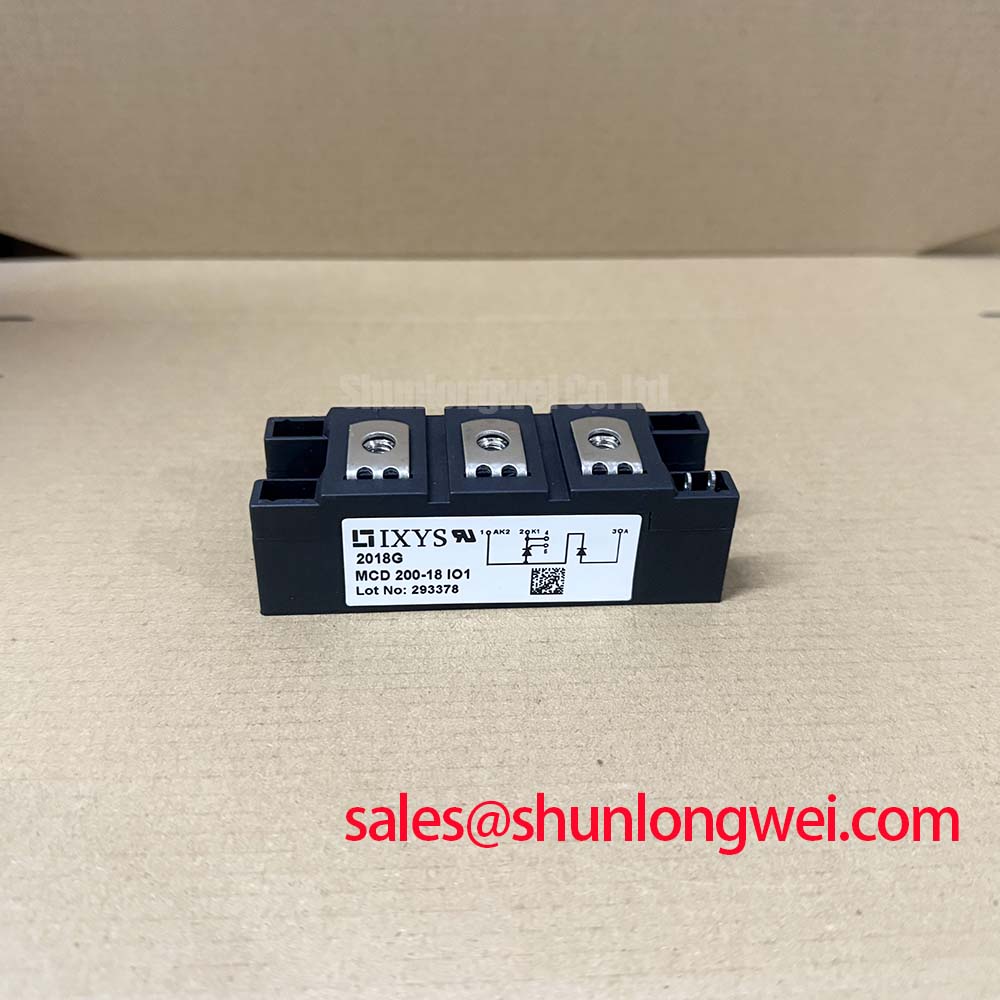
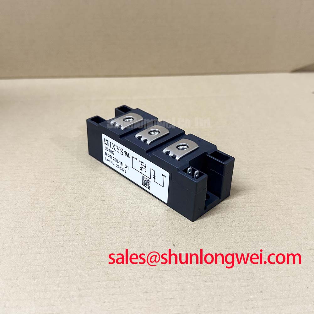
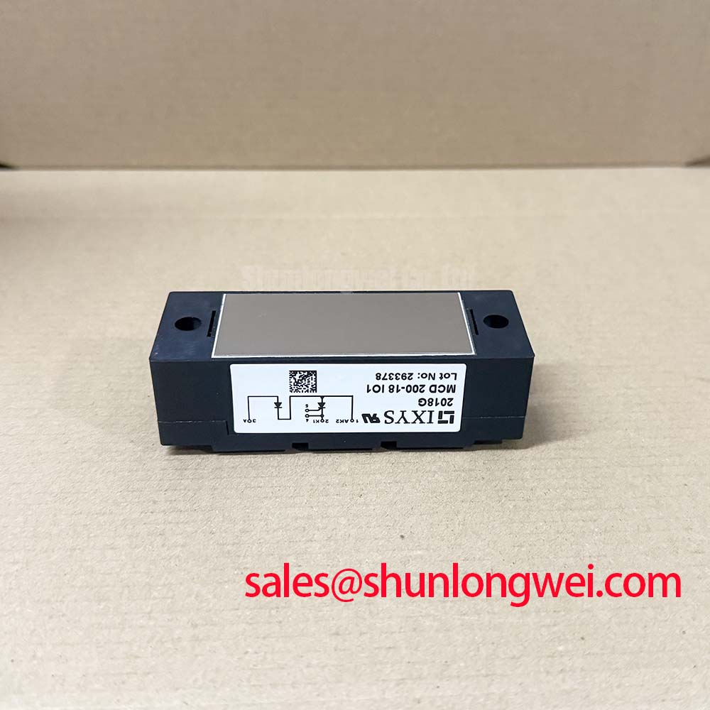
For a grid tied static Var compensator, repetitive current stress should be evaluated from the complete firing sequence rather than from the nominal branch current alone. The MCD200-18IO1 provides a 200.0 A current rating, but the permissible repetitive operating point depends on junction temperature, conduction duration, waveform, cooling conditions, and the manufacturer’s specified surge limits. The ITSM value for the installed voltage grade must therefore be taken from the relevant factory data rather than inferred from the 200.0 A rating.
During service inspection, record the phase relationship between the gate pulses and the AC waveform, then compare the result with the control system’s intended firing sequence. A missing pulse, excessive gate lead inductance, or unequal trigger timing can produce uneven triggering between the two internal thyristor paths. Engineers should verify IGT, VGT, gate reverse limits, and the permitted pulse shape from the IXYS documentation. Where the control system uses pulse trains, the pulse amplitude and duration should be confirmed at the module terminals, not only at the output of the firing board.
Fuse coordination requires the manufacturer’s published I2t data for both the semiconductor and the selected high speed fuse. The fuse clearing characteristic should be checked against the module’s allowable surge energy and the prospective fault current of the SVC branch. A fuse with a suitable voltage label is not automatically coordinated with this device. If the original fuse type is unavailable, the replacement selection should be validated by the system protection engineer using the actual network impedance and fault study.
Terminal preparation is equally important. Clean the busbar contact surfaces, inspect for discoloration or fretting, and confirm that the cable or busbar geometry does not place mechanical force on the power terminals. The applicable IXYS assembly document should govern terminal fastener type and tightening torque. Do not substitute a generic torque value for a manufacturer’s installation requirement.
Transient Dynamics & Electrical Design: AC Line Surge Immunity and Lightning Transients on MCD200-18IO1
AC line transients entering an SVC branch can be coupled through the supply network, switching apparatus, transformer leakage, or nearby lightning protection equipment. A MOV, fuse, and RC snubber should be evaluated as a coordinated protection network, not as independent accessories. The selected protection level must remain compatible with the module’s verified repetitive peak off state voltage and the actual line to line and line to earth surge environment.
IEC 61000-4-5 testing can be useful for system level surge evaluation, but a semiconductor module does not independently establish compliance with an overall equipment EMC requirement. The system integrator should define the test configuration, coupling path, protective earth arrangement, and acceptance criteria. MOV selection should account for continuous RMS voltage, temporary overvoltage, energy absorption, and ageing behavior. The clamping level must be reviewed against the module’s documented blocking voltage and the measured switching overshoot.
RC snubbers may reduce high frequency voltage ringing across the thyristor junctions, yet an incorrectly selected network can increase leakage current, heating, or repetitive switching loss. Designers should observe the voltage waveform directly at the module terminals with suitable differential measurement equipment. The busbar arrangement should minimize parasitic loop inductance so that turn off current does not create excessive inductive overshoot. Final component values remain system determined and should be confirmed during controlled switching tests.
For equipment exposed to humid or contaminated plant conditions, inspect MOV bodies, snubber resistors, terminal insulation, and enclosure barriers for tracking or surface contamination. Condensation control is a maintenance matter as well as an electrical design matter. A clean, dry enclosure and stable airflow help prevent leakage paths that can be mistaken for a thyristor blocking fault.
MCD200-18IO1 Operational Boundaries: Evaluating Uniform Heatsink Contact Pressure Limits
The TO-240AA package requires a mechanically sound thermal interface between the module base and the heatsink. Before installation, check that the heatsink surface is clean, flat, and free from burrs. The thermal compound should form a continuous interface without large voids, but the correct compound type and application method should follow the applicable assembly documentation. Excess compound can contaminate adjacent insulation and does not compensate for a distorted heatsink.
Uniform contact pressure matters because local mechanical loading can produce uneven thermal transfer across the baseplate. Tighten fasteners in the manufacturer’s specified sequence and torque range, using a calibrated tool. Where the original service documentation does not identify the torque, obtain the package assembly instruction instead of applying a generic value. The module should not be forced into alignment by the busbar; the busbar should be aligned to the installed module.
After commissioning, compare temperatures at equivalent phase connections under the same load and switching condition. A localized temperature rise may involve contact resistance, airflow restriction, compound deterioration, unequal current sharing, or a measurement error. Use an infrared camera only with a suitable emissivity reference, and confirm findings with a correctly attached temperature sensor where practical.
⚠️ Maintenance Note: Schedule heatsink cleaning and terminal inspection while monitoring contact temperature trends, because a blocked airflow path or loosening connection can increase thermal stress before an electrical trip occurs.
For preventive maintenance, inspect fan operation, filter condition, heatsink fin cleanliness, and signs of moisture or condensation. The device’s official electrical rating does not remove the need to verify the actual thermal operating point inside the cabinet. When evaluating a related component for a repair program, engineers may also compare the documented interface and ratings of TT570N16, but any substitution requires a complete voltage, current, gate drive, protection, and mechanical compatibility review.
Transient Dynamics & Electrical Design: Critical Rate of Rise of Off State Voltage on MCD200-18IO1
A rapid rise of off state voltage can produce unintended thyristor triggering when the commutation network, wiring layout, or snubber arrangement is unsuitable. The first diagnostic step is to capture the voltage at the module terminals during the real switching event. Measurements taken several centimetres away on a control cabinet bus may not represent the stress at the semiconductor terminals.
RC snubber design should consider the thyristor’s documented dv/dt capability, leakage current, repetitive switching frequency, capacitor pulse rating, resistor energy, and the surrounding AC topology. The snubber loop should be physically short, and the connection should avoid introducing a new high inductance path. Component values must be selected from measured waveform behavior and verified against temperature rise; they should not be copied from another voltage class without engineering review.
Where a series reactor or saturable reactor is considered, its saturation behavior, insulation system, fault withstand, and interaction with the SVC control sequence require system level validation. Limiting di/dt can reduce localized current crowding, but excessive impedance may affect reactive power response and commutation performance. The control engineer should review gate pulse synchronization, while the power engineer verifies peak current and voltage margins with an oscilloscope during staged tests.
For broader equipment-level guidance on semiconductor integration in demanding industrial power systems, consult the Industrial Applications reference. Although that material covers wider power semiconductor practice, the same discipline of checking switching layout, thermal paths, protection coordination, and measured operating margins is relevant when assessing this dual thyristor module.