
Content last revised on October 7, 2026
Optocoupler vs Digital Coreless Transformer Isolation in High-Voltage Switching
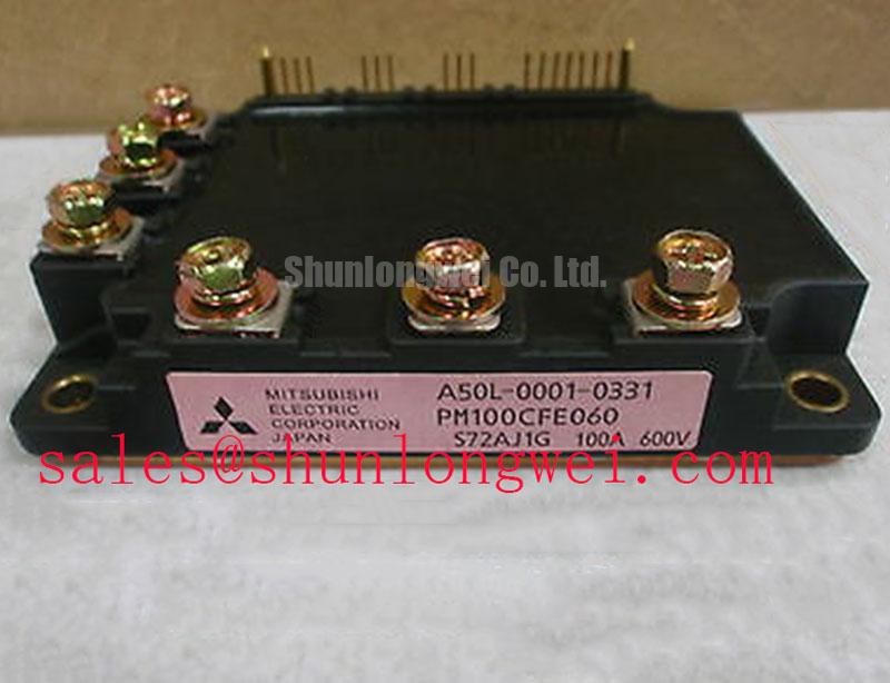
With the drive isolated and its DC link verified discharged, compare the terminal layout of the removed module with the equipment drawing before testing a PM50CS1D060 on the bench. This Mitsubishi Electric intelligent power module has an official rated voltage of 600 V, an official rated current of 50 A, and a Mitsubishi IPM Module package. Those ratings establish the first checks for a heavy-duty variable frequency AC motor drive repair; they do not establish pin compatibility or the drive’s operating margin.
Start at the drive schematic, not at the isolation technology. Trace the controller outputs through the gate-drive interface to the PM50CS1D060 control terminals, then check the return paths and auxiliary supplies against the original equipment documentation. Optocouplers and digital coreless transformers are alternative ways a surrounding control circuit may cross an isolation barrier. Neither choice identifies the isolation architecture or insulation rating of this particular module.
A false switching command can resemble a power-stage fault. As a Design Consideration, compare commanded pulses at the controller with signals observed at the driver output during controlled testing. If a discrepancy appears only while the power stage switches, examine common-mode coupling, driver supply integrity, cable routing and the board’s clearance paths. Select any required isolation rating and common-mode transient immunity from the drive’s documented voltage environment and the actual isolator datasheet; the 600 V module rating is not a substitute for either value.
Incoming inspection can establish useful baselines without energizing the power stage. Confirm terminal identities from the applicable pin drawing, check for unintended low-resistance paths, and use the meter’s diode mode only where the documented circuit topology makes its reading interpretable. An IPM contains circuitry beyond a bare IGBT, so a diode-mode result alone cannot establish gate threshold voltage or complete module health. If a static threshold measurement is required, follow a manufacturer-approved test circuit rather than applying a bench supply to an unidentified control pin.
Thermal Interface Material (TIM) Thickness Uniformity and Void Minimization
Inspect the mounting surface and heatsink contact area before transferring hardware from the failed drive. Debris, old compound and raised edges can prevent even contact. As a Design Consideration, apply the specified thermal interface material in a thin, continuous layer and use the equipment’s mounting sequence and torque specification. Do not treat a general paste-thickness or fastener-torque convention as an official PM50CS1D060 requirement. If the mating surfaces appear distorted, resolve that condition rather than using excess compound to fill the gap.
💡 Bench Tip: Keep the control terminals protected from accidental contact while cleaning the base and checking cold-state diode readings.
Before fastening the busbar, compare every power and control terminal with the original drawing and check that washers, supports and cable lugs preserve the equipment’s required creepage and clearance distances. Assess busbar fastening against the drive’s vibration requirements without transferring stress to module terminals. After mounting, verify that control connectors seat correctly and that the heatsink and surrounding metalwork do not obstruct insulation paths.
For a replacement assessment, the related CM15MD-12H can be reviewed as a separate Mitsubishi module reference, not as a confirmed drop-in substitute. Its circuit arrangement, controls, terminal positions, mounting and ratings all require independent comparison before any substitution decision.
Turn-Off di/dt Induced V_peak Clamping and Snubber Capacitor Sizing
In an operating inverter, turn-off voltage can exceed the measured DC-link voltage because current changes through stray inductance. As an Engineering Calculation, the relationship Vpeak = VDC + Lσ × di/dt explains why a short bench measurement of the DC link cannot establish the peak stress seen by a switching device. The PM50CS1D060’s official 600 V rating makes that measured peak an essential comparison, but it does not prescribe a universal snubber value or permissible busbar inductance.
For a drive that trips or shows abnormal switching waveforms, first confirm probe placement, grounding method and oscilloscope bandwidth. Compare waveforms with a documented healthy phase under equivalent conditions where that test is safe to perform. Then inspect the DC-link capacitor connections, busbar overlap and snubber connections for changes in loop geometry or loose joints. A symmetrical, compact current path is a Design Consideration for limiting inductive overshoot; final layout and clamp selection belong to the system designer and must be verified during switching tests.
Snubber capacitance cannot be selected reliably from module voltage and current ratings alone. The designer needs the drive’s bus voltage, switching conditions, measured waveform and snubber component limits. An H-bridge topology reference illustrates how switching paths and load current interact, although the repaired drive’s own schematic governs its actual topology. For measurement and fault-isolation practices, consult the Field Engineer’s Handbook alongside the equipment service documentation.
Calculating Failures-in-Time (FIT) Rates in High-Altitude Solar and Wind Farms
A defensible FIT calculation for the PM50CS1D060 cannot be made from its 600 V and 50 A ratings. It would require an applicable device reliability model or published test data, plus the installation’s voltage profile, temperature conditions, duty cycle and environment. Single-event burnout and altitude effects are likewise not quantified by the supplied module specifications. Treating an assumed failure rate or altitude derating as a product specification would obscure the actual engineering decision.
For a heavy-duty AC drive operating at an elevated site, a practical Design Consideration is to document DC-link conditions, cooling performance and measured switching peaks, then ask the equipment designer to evaluate the required margins under the site’s conditions. Keep that assessment separate from the incoming bench checks: terminal correspondence, cold-state electrical readings and physical mounting condition answer different questions. Where the motor system uses position feedback, verify the feedback device and signal path independently; an RVDT reference describes one position-sensing principle, not a feature established for this module.