

Content last revised on October 27, 2026
Field Diagnostics & Commissioning: Reverse Recovery Charge and Temperature Considerations in PT200S16A Topologies
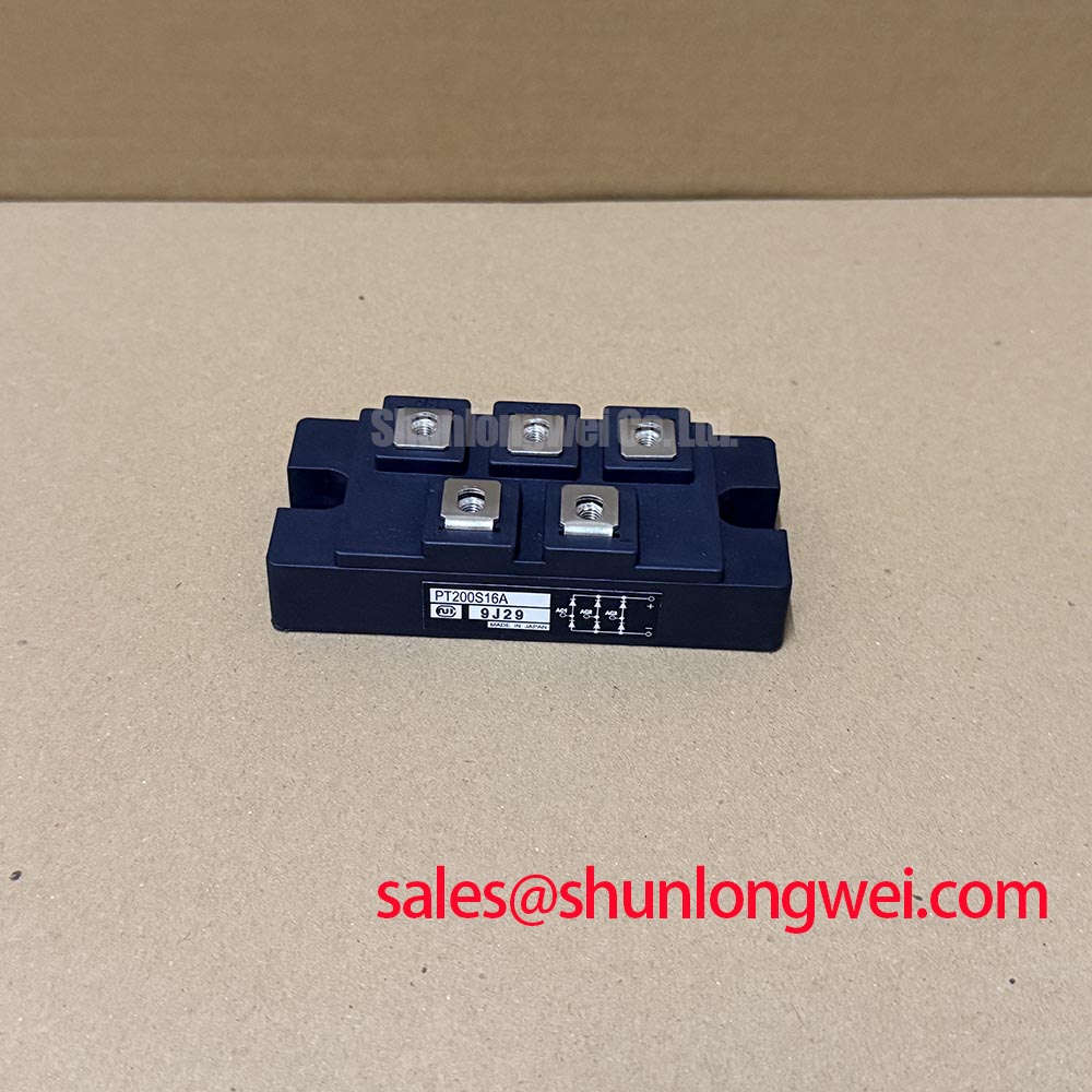
- Match the PT200S16A marking and terminal identification to the equipment schematic before disconnecting the original power wiring.
- With the assembly isolated and stored energy discharged, record cold terminal measurements in both probe polarities, noting any parallel circuit paths.
- Inspect the mounting surface, terminal hardware, and insulating surfaces for damage or contamination before preparing the heatsink interface.
- Identify the gate and cathode connections from the terminal drawing before connecting a trigger source or insulation tester.
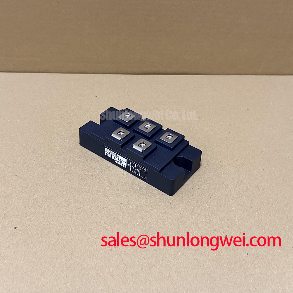
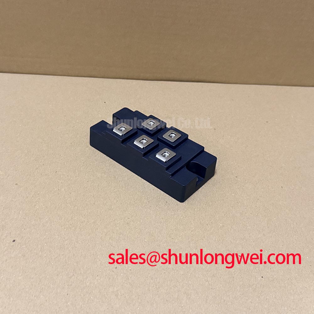
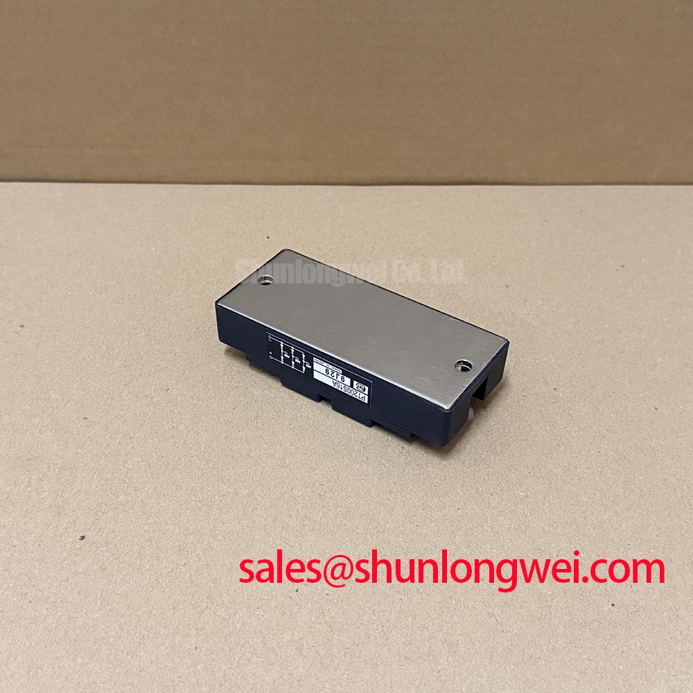
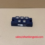
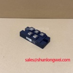
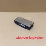
The PT200S16A from Nihon Inter (NIEC) is identified here as a Thyristor / Diode Module in an Isolated Power Module package. Incoming inspection should keep device identification, static measurements, and powered circuit acceptance as separate records.
| Product identification | Specification status |
|---|---|
| Model and manufacturer | PT200S16A; Nihon Inter (NIEC) |
| Product category | Thyristor / Diode Module |
| Package description | Isolated Power Module |
| Voltage and current ratings | Consult Datasheet for numerical ratings and associated operating conditions |
| Terminal diagram, recovery characteristics, gate limits, isolation test conditions, mounting torque, and surge I²t | Consult Datasheet before electrical acceptance or installation |
Separate diode-path screening from thyristor blocking checks before interpreting a diode-mode reading. As a Design Consideration, a multimeter can establish polarity-dependent conduction in an identified diode path, but its test current cannot characterize reverse recovery or certify a power device under operating voltage. A thyristor path can remain blocking without a suitable gate stimulus; that observation alone does not establish a fault.
Record probe polarity, terminal names, instrument mode, and device temperature alongside each reading. Comparison with a known-good assembly is useful only when connection state and measurement conditions match. Snubbers, trigger circuits, and other connected components can influence measurements, so isolate their contribution before attributing an unexpected result to the module.
For recovery assessment, a Design Consideration is to compare reverse recovery peak current, recovery time, and recovery charge under matching forward current, commutation rate, reverse voltage, and junction temperature. Recovery time alone does not establish softness. The softness factor describes the relationship between portions of the recovery waveform; interpreting it requires the manufacturer's waveform definition. Temperature-dependent changes should be evaluated from specified curves or controlled measurements, not an assumed coefficient.
Observe commutation current and device voltage with suitably rated instrumentation during authorized commissioning. Relate ringing and overshoot to the actual current path before assigning an EMI cause. The Mitsubishi Electric Diode Modules Lineup provides industry context for diode module categories, rather than evidence of PT200S16A characteristics.
PT200S16A Circuit Protection & Reliability: RC Snubber Network Optimization
Evaluate the existing snubber against measured blocking-voltage transients before changing its resistance or capacitance. As a Design Consideration, an RC network trades transient damping against discharge current and resistor dissipation. Component selection depends on circuit inductance, repetition rate, pulse loading, and the device's specified limits; it is not determined by the module designation.
Where the equipment uses a series saturable reactor, assess its current-limiting interval and reset behavior with the original circuit documentation. Its interaction with the snubber and commutation path requires system-level verification. Reducing one voltage peak does not by itself demonstrate acceptable turn-on current distribution or protection against unintended triggering.
Fuse coordination should compare semiconductor withstand data with the fuse manufacturer's total clearing I²t and peak let-through curves at the applicable fault conditions. Treat this as a Design Consideration, not a universal fuse selection rule. For mounting, use the specified terminal and base fastening instructions separately; inspect mating surfaces and preserve the intended electrical clearances.
In replacement evaluation, compare the PGH200N16 documentation against the required topology, polarity, gate characteristics, thermal interface, and mounting drawing. A related catalog entry does not establish interchangeability. A medium-frequency induction melting or hardening furnace is one potential equipment context for this assessment, subject to its rectifier and commutation requirements.
PT200S16A Gate Drive and Thermal-Electrical Optimization
Check gate current at the identified gate-to-cathode connection rather than relying solely on the trigger board output. As a Design Consideration, pulse rise, amplitude, duration, and repetition must support reliable turn-on while remaining within gate limits. The gate pulse's sustaining portion is distinct from the thyristor's main-terminal holding current; confusing them can obscure a triggering problem.
💡 Bench Tip: Use ESD precautions and record a cold baseline before powered testing, keeping the gate source disconnected during unrelated terminal measurements.
Assess driver isolation and common-mode transient immunity against measured switching disturbances. Route the gate return according to the terminal drawing, without assuming an auxiliary Kelvin connection. Keep contamination and wiring intrusion away from terminal creepage and clearance paths; an isolated package description does not establish an installation's insulation margin.
If the equipment display resets during switching, separate control-supply disturbance checks from power-device diagnosis. The The Ultimate Guide to Industrial TFT LCD Technology offers complementary display-interface context. Correlate the disturbance with gate pulses and supply behavior before changing trigger settings or replacing the power module.