

Content last revised on September 20, 2026
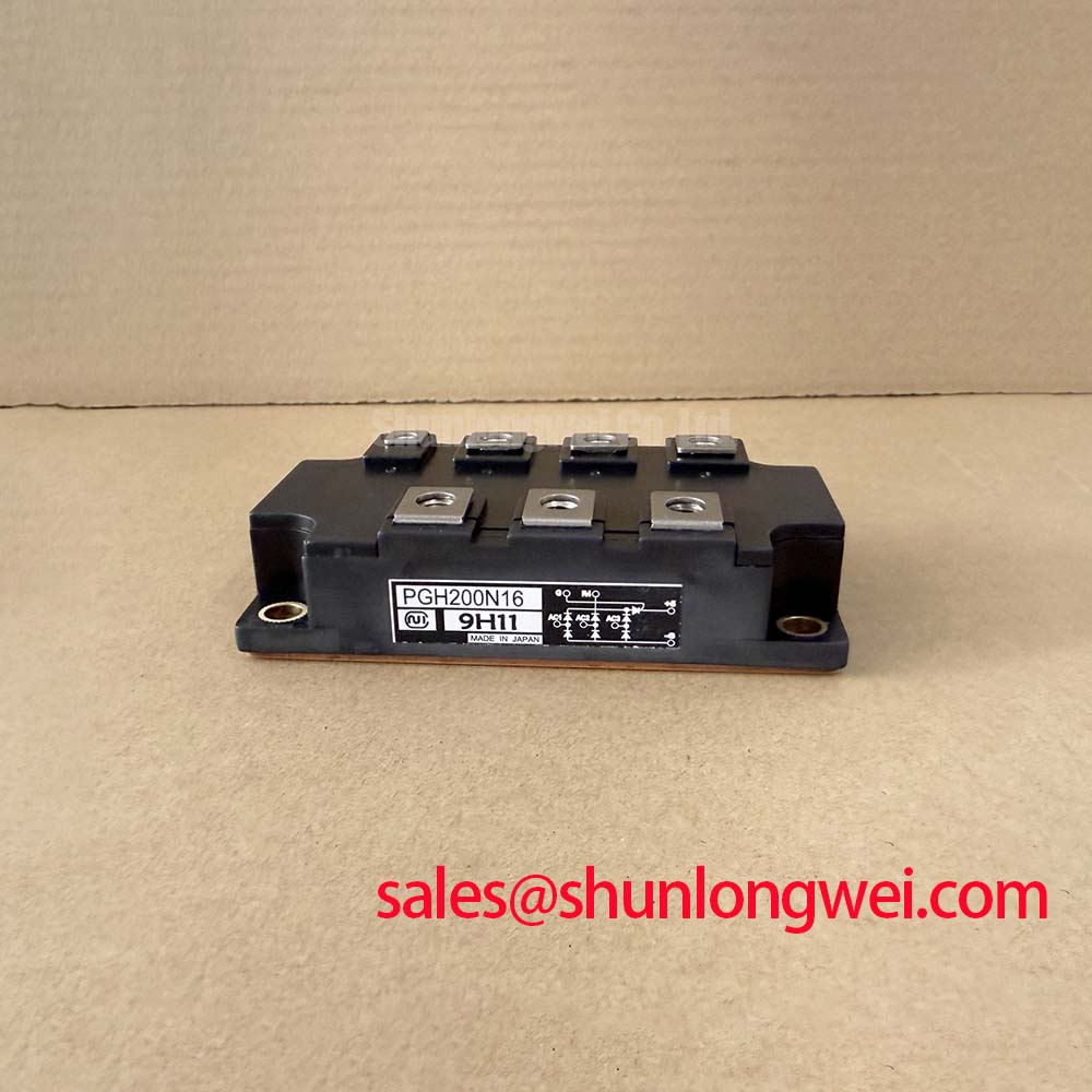
Before energizing a replacement assembly, verify that the nameplate duty does not exceed the PGH200N16 official ratings of 1600 V repetitive peak off state voltage and 200 A average on state current, then inspect the mating busbars, fuse hardware, heatsink flatness, and control wiring for signs of heat exposure or looseness.
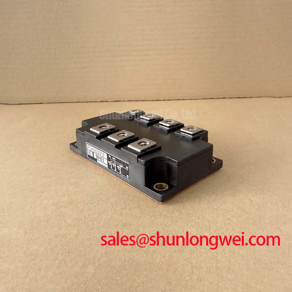
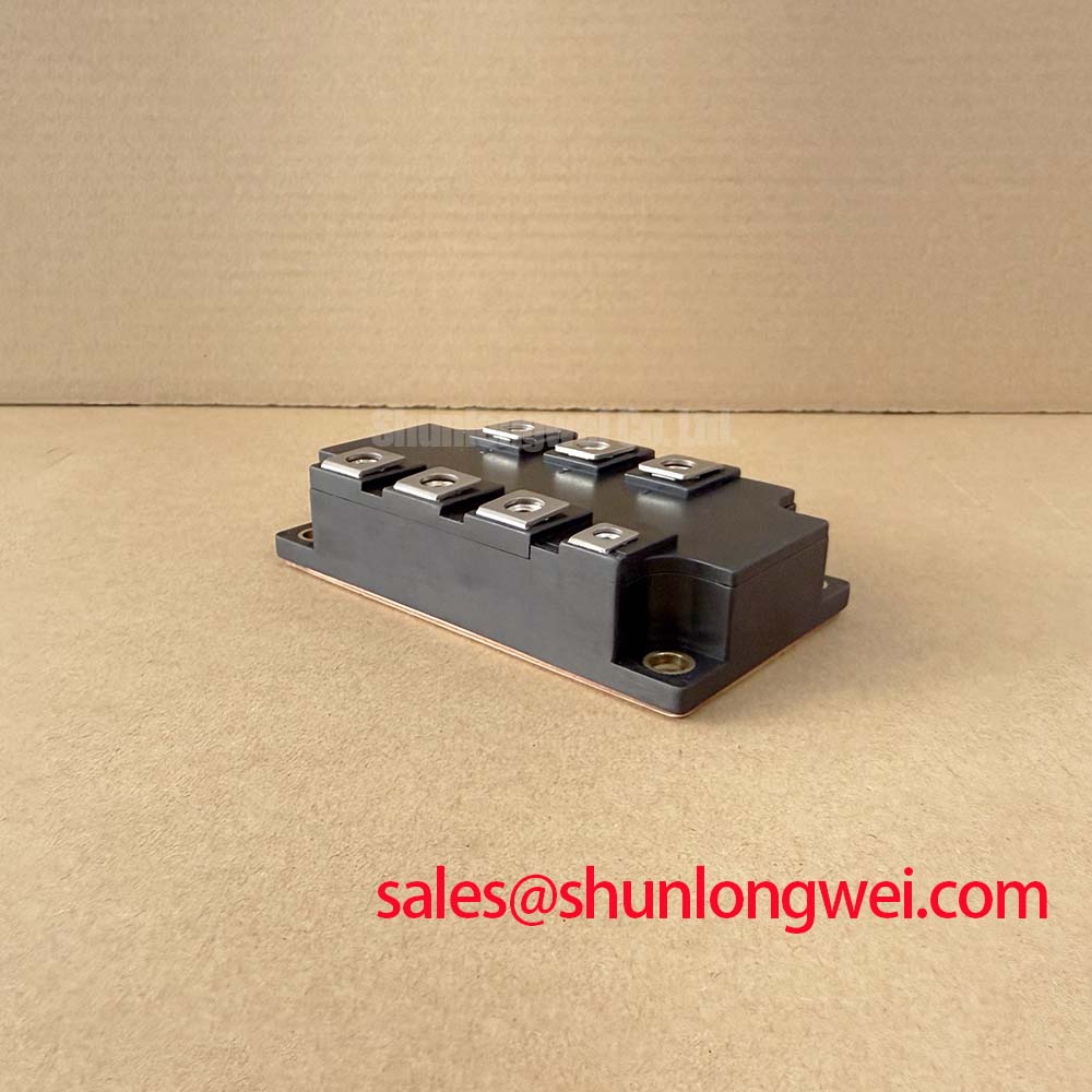
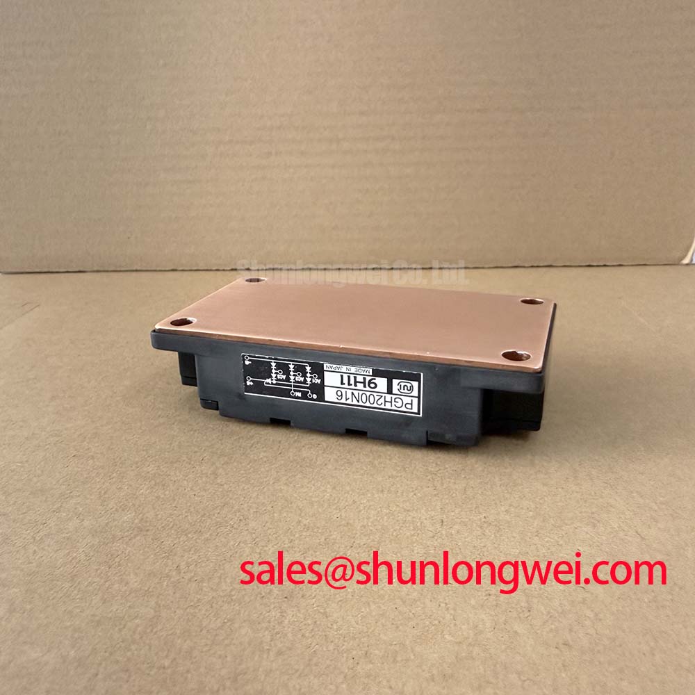
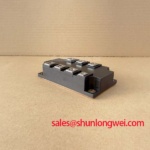
The Nihon Inter PGH200N16 is a thyristor and diode module rated for controlled high current rectification and phase angle power control. Its official 4000 A non repetitive surge current at 50 Hz provides a defined short duration surge capability, while the specified 150 mA gate trigger current is relevant when assessing compatibility with the existing firing board. The official operating junction temperature range is minus 40 degrees C to plus 150 degrees C. These ratings establish the component boundary; the surrounding control, protection, cooling, and installation details remain system dependent.
| Official Specification | Value | Integration Relevance |
|---|---|---|
| Repetitive peak off state voltage | 1600 V | Defines the official blocking voltage boundary for the device. |
| Average on state current | 200 A | Supports evaluation of continuous current duty in the installed circuit. |
| Non repetitive surge current | 4000 A at 50 Hz | Relevant to short duration fault and inrush coordination. |
| Maximum gate trigger current | 150 mA | Relevant to verification of the gate firing circuit capability. |
| Operating junction temperature | minus 40 degrees C to plus 150 degrees C | Defines the official semiconductor temperature operating range. |
PGH200N16 Operational Boundaries: Preventing Localized Gate Hotspot Burnout
A phase controlled soft starter should be assessed as a complete power path before a PGH200N16 is installed. Check that the incoming line sequence, controlled phase positions, load terminals, gate and return wiring, and bypass contactor logic agree with the original schematic. A gate lead connected to the wrong control channel can produce an apparently intermittent phase loss, while a poor gate return connection can make firing behavior depend on vibration, enclosure temperature, or adjacent phase activity.
The 150 mA specified gate trigger current is an electrical characteristic, not a recommended firing pulse setting. It should not be converted into a fixed gate drive prescription without the original firing board documentation and the relevant device curves. Design Consideration: gate pulse rise time, pulse width, repetition pattern, gate return routing, and the voltage available from the isolated firing stage should be reviewed together. A controlled thyristor must receive a firing signal that is appropriate for the actual anode current, junction temperature, line position, and electrical noise conditions present in that starter.
Where a multi pulse firing scheme is used, commissioning should confirm that pulse activity is synchronized to the intended phase angle and that pulses disappear correctly when the controller removes the run command. This is especially useful after a firing board replacement or a control transformer repair. Record phase voltage and gate activity with appropriately rated isolated measurement equipment, then compare each phase against a known healthy channel. Unequal conduction can arise from several locations, including firing electronics, line conditions, load imbalance, contact resistance, cooling differences, and the module itself. The measurement record is more useful than assigning a single cause from one symptom.
The official 200 A average on state current rating must be considered alongside the actual conduction angle and enclosure thermal path. In a soft starter, current does not tell the full thermal story by itself because the phase angle program changes the conduction interval during acceleration. Designers and maintenance teams should verify the thermal interface condition, heatsink cleanliness, airflow path, and temperature response under the actual motor starting profile. The stated minus 40 degrees C to plus 150 degrees C operating junction range is an Official Specification; it does not remove the need to control condensation, contamination, or blocked airflow in the panel.
Maintenance Note: De energize and verify the DC and AC energy sources are absent before removing gate leads or retightening power connections, because retained energy and incorrect reconnection can damage the firing circuit.
Design Consideration: periodic maintenance should include clearing dust from the heatsink fins and cooling path, inspecting aged thermal interface material for drying or displacement, and checking terminal tightness against the equipment manufacturer’s documented assembly requirement. Do not assign a mounting torque to this module from a generic rule when the applicable hardware, washer stack, busbar thickness, and heatsink arrangement have not been confirmed. Uneven mechanical loading can raise interface resistance and produce temperature imbalance between otherwise similar phase positions.
For a lower current repair assessment, the related PGH50N16 has to be evaluated against the original circuit’s voltage class, current duty, gate circuit requirements, mechanical arrangement, thermal path, and protection coordination. A shared voltage designation alone does not establish interchangeability.
Transient Dynamics & Electrical Design: Fuse Total Clearing I2t versus Device Melt on PGH200N16
During a dead short investigation, begin with the installed semiconductor fuse part number, its manufacturer curve, the fuse holder condition, and the upstream protective arrangement. The PGH200N16 official surge rating is 4000 A at 50 Hz for non repetitive conditions. It must not be interpreted as an available fault clearing rating, a repetitive overload allowance, or a substitute for properly coordinated semiconductor protection.
Fuse coordination requires data that is not included in the supplied PGH200N16 specifications: the fuse pre arcing characteristic, total clearing I2t, prospective fault current, supply impedance, fault location, conductor contribution, and the device’s applicable overload or I2t capability from the original manufacturer documentation. Engineering Recommendation: compare the complete fuse clearing behavior with the permitted device withstand information in the applicable data set, then validate the assembled protection chain for the real supply. Without those source values, declaring that a fuse will prevent device rupture would be unsupported.
Physical inspection has practical value after a fault. With equipment isolated, examine fuse clips, busbar joints, insulator surfaces, cable lugs, and control connectors for discoloration, carbon tracking, loosened hardware, or deformation. A fuse can operate because of a downstream fault, but it can also be affected by poor connection resistance or an installation issue. Check each power connection against the original equipment assembly documentation rather than relying on appearance alone.
Transient overshoot depends on the current change, source impedance, loop geometry, snubber condition, and wiring layout. Design Consideration: minimize parasitic loop inductance where it can contribute to turn off or commutation overshoot, then verify peak voltages against the 1600 V official repetitive peak off state rating during correctly rated switching tests. This establishes an evidence based margin assessment for the installed topology rather than applying a generic numerical rule.
Soft starter cabinets sometimes include rectification or auxiliary DC sections that are separate from the controlled AC phases. The FRS200CA100 can be reviewed as a related rectifier stage component where the original circuit documentation identifies that function. Its electrical ratings, topology, heatsinking, and connection arrangement should be checked independently from the PGH200N16.
Field Diagnostics & Commissioning: Phase Angle Voltage Profiling in PGH200N16 Topologies
For a high voltage three phase motor solid state soft starter, commissioning should start with a controlled review of the phase angle command, motor data, current feedback scaling, acceleration sequence, overload settings, bypass transfer logic, and load condition. Locked rotor current in induction motor systems is commonly much higher than rated running current, but the actual level and acceptable starting profile are determined by the motor design, driven load, supply stiffness, and starter control strategy. Do not apply a universal current multiple as a commissioning target.
Use appropriately rated instruments to observe phase to phase voltage development and current symmetry through the start cycle. A healthy profile normally shows coordinated progression across the three controlled phases in accordance with the controller program. A delayed or irregular phase response may indicate a control timing issue, a gate drive concern, a power connection problem, an imbalance in the incoming supply, or a load related condition. Compare against the original waveform expectation or a known good unit before replacing a power module.
The PGH200N16’s 200 A average on state current remains the relevant Official Specification for continuous current evaluation, but motor starting imposes a time varying electrical and thermal duty. Engineering Recommendation: have the system engineer evaluate the acceleration duration, starts per operating cycle, bypass contactor behavior, ventilation condition, and measured heatsink temperature trend. This is particularly important where a process change has increased load inertia or where a starter is repeatedly cycling without enough cooling recovery time.
For assemblies that use controlled rectification, regenerative braking, or a braking resistor branch elsewhere in the machine, trace the function through the approved electrical drawing. A braking resistor and its switching path absorb energy only when the system topology and controller command support that function. The PGH200N16 should not be described as a braking chopper without source documentation showing it occupies that role. The same discipline avoids confusing a phase controlled soft starter module with a DC drive armature bridge or a line rectifier.
Gate drive margin deserves special attention during low temperature starts and after control board servicing. The specified 150 mA gate trigger current identifies an electrical characteristic, while the needed firing behavior must be verified from the original module documentation and drive circuit design. For practical maintenance and test context on preventing unintended switching in gate controlled power devices, see Evolution of Negative Off-Bias Gate Drive Circuits. Its concepts should be applied only where they match the actual device type and firing architecture.
PGH200N16 Circuit Protection & Reliability: Calibrating IEC 61000-4-5 Industrial Surge Immunity
IEC 61000-4-5, rather than IEEE 61000-4-5, is the commonly referenced surge immunity standard for equipment level testing. A PGH200N16 module is not, by itself, an IEC 61000-4-5 certified assembly. Surge behavior depends on the incoming protection network, enclosure wiring, earthing, cable entry arrangement, control isolation, line impedance, and the selected test conditions. Any equipment compliance claim must therefore be supported by testing of the completed product.
The 1600 V repetitive peak off state voltage is the official blocking voltage specification to retain as the primary device limit during surge and commutation analysis. It should not be presented as a guarantee of survival against an arbitrary incoming surge. Design Consideration: evaluate the location and coordination of MOV protection, RC snubbers, fuses, contactors, and isolation barriers so that the actual transient at the module terminals is characterized during system validation.
An MOV clamps voltage by becoming more conductive as the applied voltage rises, while its response and service condition depend on its selection, energy exposure, ambient environment, and upstream protection. The physical basis is described by Varistor transient overvoltage protection physics. A deteriorated MOV, cracked snubber capacitor, or open snubber resistor can alter the transient profile, but inspection alone cannot establish the exact waveform. Verify the protection path using the original circuit documentation and suitable measurements.
For short circuit planning, short circuit withstand time is a device specific parameter that must come from the applicable official documentation. The supplied PGH200N16 parameter set does not state such a value. The ROHM short circuit withstand time guidelines offer general context for power semiconductor protection practice, but they must not be transferred as a PGH200N16 rating. Preserve the separation between a manufacturer’s published module specification, an Engineering Calculation using complete fuse and fault data, and a Design Consideration for the installed equipment.
Reliability work in an operating cabinet is often straightforward but should be disciplined: maintain clear airflow, keep moisture and condensation away from live assemblies, inspect thermal interfaces during scheduled shutdowns, verify terminal contact condition, and record temperature changes after repairs. These actions support repeatable maintenance decisions without inventing lifetime predictions, failure rates, EMC claims, or environmental qualification statements that are not provided for this module.