Content last revised on September 14, 2026
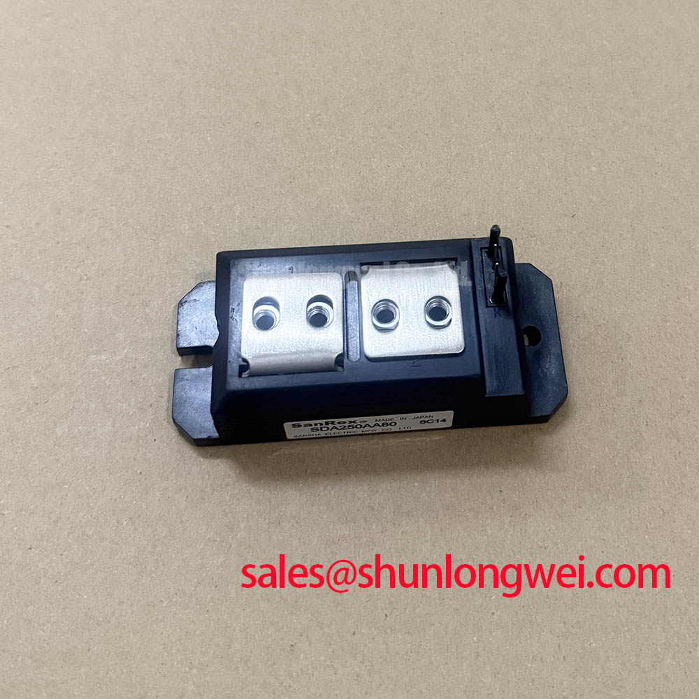
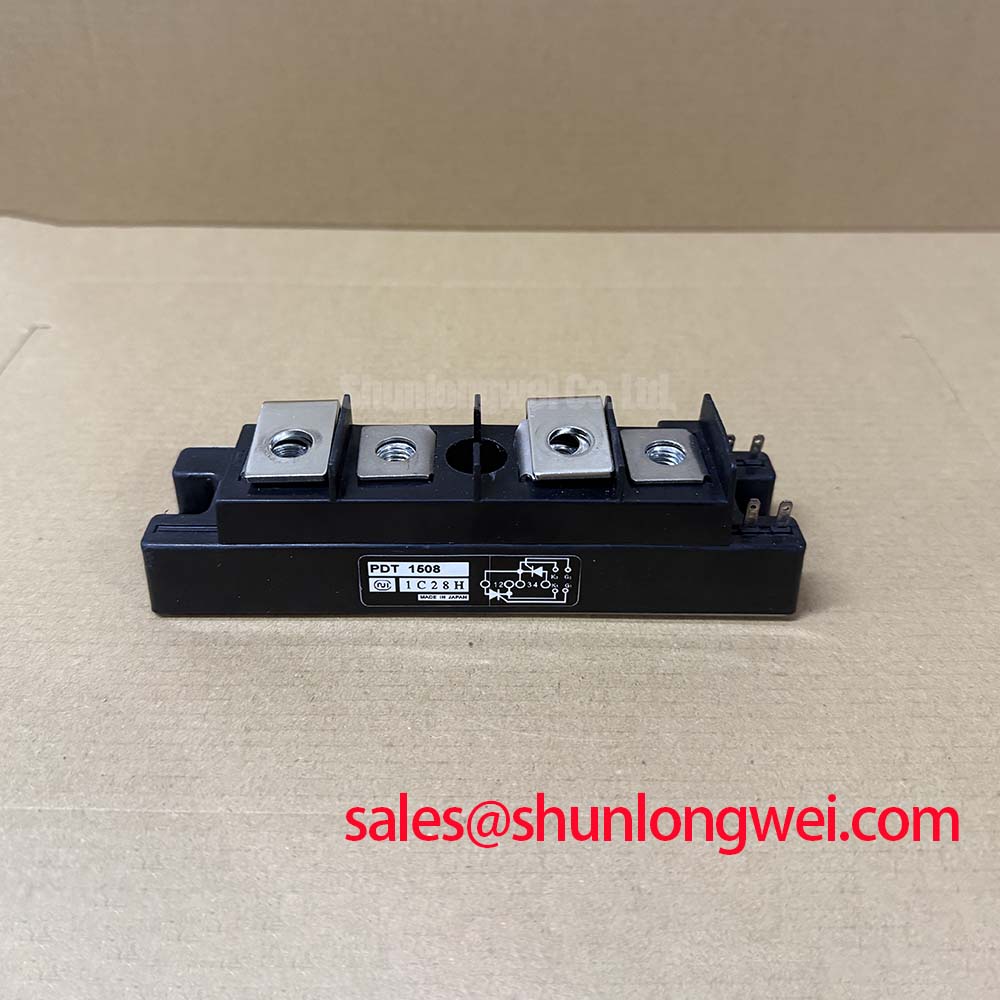
FRS200CA100 SanRex 1000 V 200 A Thyristor Diode Module
Begin service inspection by isolating the equipment, confirming the nameplate rating, checking the module body for cracks or discoloration, and verifying that the terminal arrangement matches the original installation before applying any test voltage. The FRS200CA100 is a SanRex, also identified with Sansha Electric, thyristor and diode module specified for applications where controlled high current and reverse voltage capability are required.
Its published electrical limits include a 1000 V repetitive peak reverse voltage and a 200 A average forward current at Tc = 78°C. These values describe the semiconductor rating under the stated datasheet conditions. They do not replace a system-level assessment of line voltage, conduction angle, enclosure temperature, cooling airflow, overload profile, or switching transients.
| Parameter | Official Specification |
|---|---|
| Repetitive peak reverse voltage, VRRM | 1000 V |
| Average forward current, IF(AV) | 200 A at Tc = 78°C |
| Maximum forward voltage drop, VFM | 1.8 V at IF = 200 A |
| Maximum reverse recovery time, trr | 350 ns |
| Surge forward current, IFSM | 3300 A, one half cycle at 60 Hz |
| I2t surge value | 45000 A2s for one cycle of surge current |
| Maximum junction to case thermal resistance, Rth(j-c) | 0.20 °C/W |
| Isolation breakdown voltage, VISO | 2500 V AC for 1 minute |
The 1.8 V maximum forward voltage at 200 A is an official specification and should be treated as a significant thermal design input. Actual heat dissipation depends on the operating current waveform and conduction interval, not only on the nominal current rating. In a high voltage three phase motor solid state soft starter, the maintenance team should review the heat sink condition, airflow path, phase balance, and the measured temperature rise during a representative starting cycle.
Transient Dynamics and Electrical Design for the FRS200CA100
When the FRS200CA100 is evaluated in a high voltage three phase motor solid state soft starter, the first electrical task is to map each power terminal to the original schematic and confirm that phase, line, and load connections have not been interchanged. The module’s 1000 V VRRM rating is a factory limit for repetitive peak reverse voltage. It is not a blanket allowance for uncontrolled line transients. Designers should verify the highest repetitive and nonrepetitive voltage appearing across the semiconductor during firing, commutation, motor interruption, and fault clearing.
RC snubber selection is a Design Consideration governed by the measured switching waveform, leakage current, available damping, and the voltage and pulse-current capability of the selected components. The network should be evaluated to reduce unwanted voltage rate of rise and ringing at the semiconductor terminals. The resistor and capacitor values must be determined from the complete circuit, including wiring inductance, transformer impedance, motor cable length, and the installed protection network. Oscilloscope measurements with suitable high-voltage differential probes should be used to verify the result during startup and controlled shutdown.
A saturable reactor or other series impedance may be considered when the installation requires additional control of current rise during abnormal or high-inrush conditions. This is an Engineering Recommendation rather than an FRS200CA100 factory parameter. The system engineer should verify current sharing, conduction-angle behavior, acoustic effects, and thermal performance after any series element is added.
The specified 350 ns maximum reverse recovery time is relevant when reviewing commutation overlap and transient interaction with other semiconductor stages. It should not be used alone to predict the complete soft starter waveform. If the upstream rectifier or auxiliary power stage requires coordination, engineers may also review TD210N12 as a separate, objectively specified device. Its suitability must be established from the actual circuit requirements rather than assumed from product category.
Assembly Integrity and High di/dt Firing Layout
Reliable operation begins with a clean mechanical interface. Before installation, remove contamination from the heat sink mounting surface, inspect the mating face, and confirm that the thermal interface material is evenly distributed without trapped debris. The module’s published Rth(j-c) maximum of 0.20 °C/W applies to the junction-to-case path. It does not include thermal resistance through the interface material, mounting surface, heat sink, cabinet air, or cooling system.
Mounting hardware and terminal connections should follow the SanRex installation documentation for the exact package. Do not substitute an estimated tightening value when the original assembly record or manufacturer mechanical drawing is available. The mounting surface should remain flat and clean, while busbars should be supported so that terminal stress is not transferred into the module body. After commissioning, a controlled thermal survey under load can help identify unequal phase heating or a connection with abnormal temperature rise.
Gate firing layout is a Design Consideration that depends on the firing circuit, pulse transformer or driver arrangement, cable routing, and the verified terminal definition of the specific module. Keep firing conductors separated from high-current commutation paths where practical, minimize the loop area, and confirm that the return path follows the intended circuit reference. A fast pulse edge or multi-pulse strategy should be selected only after checking the gate requirements in the applicable manufacturer documentation.
Because the supplied product data does not define a gate pulse current, gate rise-time limit, holding current, or back-porch timing value, those quantities should not be presented as fixed FRS200CA100 specifications. The commissioning engineer should observe the firing waveform at the module interface and compare it with a known-good phase. Any suspected timing mismatch should be investigated alongside line imbalance, control reference integrity, insulation condition, and terminal voltage.
High voltage clearance and creepage are determined by the complete assembly, not by the semiconductor rating alone. The panel designer should verify spacing around exposed terminals, barriers, busbars, and mounting hardware against the applicable installation standard, working voltage, pollution environment, altitude, and enclosure construction. Moisture and condensation control are equally important in equipment stored or operated through large temperature changes.
Maintenance Note: De-energize and discharge the system before touching terminals, and periodically check heat-sink cleanliness, airflow, thermal-interface condition, and terminal tightness using the approved plant procedure.
Semiconductor Protection Fuse Selection for the FRS200CA100
Fuse coordination should be based on the complete prospective fault-current study and the semiconductor protection fuse manufacturer’s clearing data. The FRS200CA100 has an official IFSM rating of 3300 A for one half cycle at 60 Hz and an official I2t value of 45000 A2s for one cycle of surge current. These ratings provide reference points for short-duration surge capability, but they do not guarantee survival during every fault condition.
For a protection review, compare the fuse let-through I2t and clearing time with the applicable semiconductor withstand data, while also checking peak let-through current, prospective RMS current, system voltage, available short-circuit current, and coordination with contactors or disconnect devices. The 45000 A2s figure should not be treated as a universal fuse selection limit because fuse construction, pre-arcing behavior, current waveform, and installation impedance affect the actual energy delivered to the module.
A dead-short event can also impose mechanical and thermal stress on busbars, lugs, heat sinks, and enclosure components. The protection study should therefore assess the entire fault path rather than focusing on the module alone. Selective coordination, interrupt rating, fuse orientation, and replacement access should be documented in the equipment maintenance file.
When comparing another SanRex device such as PK55FG120, engineers should compare voltage class, current conditions, package geometry, terminal configuration, thermal data, firing requirements, and protection coordination point by point. A similar appearance or nominal current value does not establish interchangeability.
The module’s 2500 V AC isolation breakdown voltage for one minute is an official insulation test rating. It should not be interpreted as the permitted continuous working voltage between every exposed part of the finished assembly. System insulation verification should account for creepage, clearance, pollution, wiring support, test method, and the relevant equipment standard.
AC Input Transient Overvoltage Clamping Guidelines
AC input protection should be assessed at the equipment boundary before selecting MOVs, RC networks, or other surge-limiting components. The protection arrangement must match the supply configuration, transformer impedance, earthing system, prospective fault current, and expected surge environment. IEEE 61000-4-5 may be used as a reference for surge immunity testing, but passing a system test cannot be claimed from the presence of this semiconductor alone.
A MOV network is a Design Consideration for limiting transient voltage, while its continuous operating voltage, energy rating, clamping behavior, failure mode, and backup protection must be selected from the actual line conditions. The chosen clamp level should remain compatible with the FRS200CA100’s published reverse voltage boundary and with the insulation coordination of the complete soft starter. Engineers should validate residual voltage at the semiconductor terminals during representative surge and switching tests.
RC suppression placed near the power terminals can help control ringing when its impedance and pulse capability are suitable for the circuit. Long wiring between the suppression network and the module can reduce effectiveness by adding parasitic inductance. Keep the high-current path compact, provide secure mechanical support for busbars, and route control wiring away from the highest transient-current loops.
Where additional surge suppression is required, the general operating principles of TVS diodes for surge protection may be reviewed, although a TVS diode is not automatically suitable for a high-power AC motor starter. Component selection must consider bidirectional AC operation, repetitive energy, thermal behavior, and coordination with upstream protection.
For service teams, record the measured line-to-line and line-to-earth waveforms, phase firing behavior, terminal temperature, and insulation test results after maintenance. The SanRex Sansha Electric power semiconductor reference should be consulted for manufacturer-level product information, while application-specific verification remains the responsibility of the equipment designer and service organization. Additional troubleshooting practices can be organized with the Field Engineer’s Handbook.