

Content last revised on September 18, 2026
Transient Dynamics & Electrical Design: AC-to-DC Transfer Characteristics of FRS300BA50
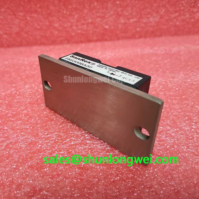
Before removing a failed unit, isolate the equipment, discharge the DC link according to the machine service procedure, and compare the installed nameplate, terminal arrangement, and cold terminal resistance against the circuit diagram. FRS300BA50 is identified as a SanRex, also known as Sansha Electric, power semiconductor module with an official rated current of 300.0 A and a SanRex Power Module housing. The available product record describes its voltage class only as Standard Industrial Rating; the exact voltage class must be verified from the original equipment documentation and the applicable manufacturer datasheet before it is connected to an AC supply or DC bus.
The model designation alone should not be used to infer a firing angle range, device topology, fuse coordination value, isolation rating, or terminal function. These details determine whether a power module is used in a controlled rectifier, a freewheeling path, or another power conversion position. In an induction melting or hardening furnace power supply, the maintenance engineer should trace each large conductor back to the transformer secondary, DC link, commutation network, or load circuit before deciding how the module participates in AC to DC transfer.
For controlled conversion, changing the firing command changes when current is admitted from the AC source. That timing can alter the average DC output, source current waveform, reactive power demand, and transformer loading. These are system characteristics rather than official characteristics of FRS300BA50. A firing angle from 0 degrees through 150 degrees can only be assessed after confirming the device circuit, supply waveform, gate drive reference, and load current continuity with the original power schematic.
Design Consideration: use an isolated measurement method appropriate to the equipment while checking the firing sequence. Compare the intended phase relationship with a known good channel, and observe whether the output voltage or current departs from the expected converter waveform. A distorted waveform can arise from several conditions, including a missing command pulse, a faulty synchronization reference, a loose power connection, an upstream fuse issue, a transformer problem, or a fault elsewhere in the commutation path. The module should not be assigned as the sole cause without those checks.
At 300.0 A, the integrity of bolted current paths is operationally important. Inspect contact surfaces for heat marking, displaced hardware, contamination, and evidence that a cable lug has moved under mechanical stress. Verify the torque requirement from the module documentation and the equipment manufacturer’s service information. No official mounting torque, fuse I2t value, surge current rating, or junction temperature limit has been provided for this product record, so these values should not be substituted from a visually similar module.
Field Alert: Do not energize a replacement module until every power terminal and control connection has been restored to the documented position and mechanically secured to the specified hardware requirement.
When an equipment repair calls for a comparison part, FRS200CA100 is a separate module that should be evaluated only by its own official electrical rating, package drawing, terminal layout, and circuit role. Matching a family prefix or physical outline does not establish replacement compatibility. The original system voltage class, continuous and cyclic current duty, cooling interface, control method, and protection arrangement remain the decision points.
| Identification item | Recorded specification | Classification |
|---|---|---|
| Model | FRS300BA50 | Official product identification |
| Manufacturer | SanRex, Sansha Electric | Official manufacturer identification |
| Rated current | 300.0 A | Official Specification |
| Voltage class information | Standard Industrial Rating | Official product record wording |
| Housing | SanRex Power Module | Official Specification |
For background on common module arrangements, Power Module Architecture & Topologies provides a general reference. The circuit diagram and product specific documentation take precedence over a general topology description during service work.
FRS300BA50 Thermal-Electrical Optimization: Dynamic Voltage Sharing and RC Damping in Practical Tuning
With the system deenergized, inspect the mounting plane before fitting FRS300BA50. A warped heat sink, burr, trapped debris, damaged thread, or uneven contact pressure can compromise heat transfer and create misleading electrical symptoms after startup. Confirm that the replacement module sits flat, that the hardware suits the documented mounting arrangement, and that any thermal interface material is applied according to the equipment service instructions. The supplied product information confirms the power module housing but does not state a permitted mounting torque, thermal resistance, baseplate flatness tolerance, or cooling requirement.
Design Consideration: a controlled rectifier or commutated power circuit can develop transient voltage stress from transformer leakage inductance, bus inductance, cable routing, and the switching behavior of the surrounding devices. An RC damping network is normally assessed as part of the complete circuit to control ringing and reduce unwanted voltage excursions. The correct resistance and capacitance depend on the measured waveform, the actual voltage class, pulse conditions, physical layout, component ratings, and allowable dissipation. These values cannot be derived from the stated 300.0 A current rating alone.
Where multiple devices share voltage in a series arrangement, equal sharing depends on the designed network, gate timing, component behavior, layout symmetry, and operating condition. It should be verified with suitably rated instruments while the machine is operated under a controlled test condition. Do not assume that adding a generic snubber will correct unequal voltage distribution. An incorrectly selected network can add loss, alter commutation behavior, or conceal a wiring issue without resolving it.
A saturable reactor, where present in the original design, is likewise a system component rather than an interchangeable accessory. Its magnetic behavior, current path, saturation point, thermal condition, and mechanical mounting influence the current rise during commutation. Engineers should retain the original circuit intent, verify its condition, and test peak voltage and current margins in the real equipment before changing reactor or damping components.
The first useful post installation check is usually comparative. Measure the waveform at equivalent circuit points on a known good channel and on the repaired channel, using probes and connections appropriate to the voltage and energy involved. Observe the timing relationship between command signal, phase voltage, load current, and any snubber response. A difference may indicate a drive issue, connection impedance, defective passive component, or changed power path. It does not establish a single cause without corroborating measurements.
Fuse selection and I2t coordination require the fuse manufacturer data, the original protection design, expected fault clearing behavior, conductor capability, and the module’s official surge and overload limits. No fuse I2t coordination table has been supplied for FRS300BA50. Keep the protection arrangement documented for the specific furnace power cabinet, and do not transfer a fuse value from another current class solely because both modules are installed in industrial power equipment.
For contextual manufacturer information, consult SanRex Sansha Electric Power Semiconductor Modules. Product specific documentation remains necessary for terminal assignment, blocking characteristics, thermal limits, and any manufacturer approved assembly conditions.
Benchtop Waveform Tuning: Mitigating Stress via High-Frequency Switching Loss Dissipation on FRS300BA50
Start a waveform investigation by identifying whether the repaired cabinet uses a line commutated controlled rectifier, a chopper, an inverter stage, or a mixed topology. The requested examination of reverse recovery peak current, reverse recovery time, recovery softness, switching loss, and radiated interference only applies where the actual circuit includes a diode commutation event or another device transition that produces those effects. The product data provided for FRS300BA50 does not specify diode reverse recovery parameters, gate characteristics, switching frequency, or loss curves. Those values must be obtained from the applicable official documentation before they are used in a tuning decision.
In practical bench testing, record the waveform before altering a damping network or control delay. Use the original circuit drawing to identify the reference point and current path. Compare the repaired channel with an equivalent channel where possible. A sharp current transition or voltage ringing can be affected by probe grounding, measurement bandwidth, busbar geometry, cable routing, snubber condition, source impedance, and switching timing. Confirm the measurement setup before interpreting a narrow spike as an equipment failure.
Design Consideration: minimize the physical loop area of high current commutation paths when reassembling the original layout. This helps reduce parasitic inductance that can contribute to turn off overshoot and ringing. The system engineer should verify peak margins against the actual DC link voltage during controlled switching tests. The same principle applies to a long motor cable or output cable, where transmission line reflections can produce a voltage peak at the far end. The required filter arrangement depends on cable characteristics, load, inverter edge rate, insulation system, and measured waveform.
Soft recovery is a descriptive waveform behavior, not a guaranteed property that can be assigned to this module without the relevant official curve. A recovery profile that changes between channels may point to differences in current, temperature, companion devices, or circuit inductance. Check the complete commutation path, including terminals, return conductors, suppression components, and any parallel branches. Avoid declaring an EMI compliance result from a component waveform. Electromagnetic compatibility is assessed at equipment level with the final enclosure, wiring, grounding, controls, and operating modes.
For an induction heating supply, test work should be staged from low risk conditions defined by the equipment procedure toward the normal operating condition. Verify that cooling flow, interlocks, phase sensing, control feedback, and protective shutdown functions are active before sustained power operation. The stated 300.0 A rating is an official module parameter, but it does not replace evaluation of the complete current waveform, duty cycle, thermal path, or system protection response.
If a rectifier stage is being examined alongside the controlled power stage, PK55FG120 can be referenced as a separate associated power semiconductor product. Its use in a particular circuit must be established through its own specifications and the equipment schematic, rather than assumed from a general relationship between rectification and power control.
FRS300BA50 Operational Boundaries: Evaluating High-di/dt Gate Firing: Pulse-Train Timing Limits
Before evaluating firing pulses, establish whether FRS300BA50 has gate terminals in the installed circuit and confirm their designation from official product documentation. The supplied parameters identify a SanRex power module rated at 300.0 A, but they do not state gate trigger current, gate voltage, holding current, latching current, pulse rise time, allowable gate current slew rate, pulse width, or multi pulse firing requirement. These electrical boundaries cannot be responsibly inferred from the current rating, the package name, or an adjacent module on the same heat sink.
For a gate controlled circuit, inspect the command wiring and connector retention with power removed. Look for broken conductors, loose terminals, moisture exposure, damaged insulation, and incorrect routing near high current paths. Then compare the command waveform at the relevant control reference with the waveform of a functioning channel. The comparison should include synchronization position, pulse presence, pulse repetition, and timing stability under the machine conditions defined by its service procedure. A missing or displaced pulse can be caused by the gate drive, synchronization circuit, interlock logic, cable connection, or the module itself.
Design Consideration: the gate drive and its return path should be treated as a controlled interface. Noise coupled from the main power loop can alter the apparent gate waveform and can affect firing behavior in sensitive layouts. Maintain the original routing and shielding practices, minimize unintended coupling, and verify behavior under switching conditions with equipment appropriate to the circuit. Any change to gate resistance, pulse transformer arrangement, firing board settings, or pulse train timing should be validated by the system engineer against the official device limits and the complete converter response.
Terms such as back porch holding current and gate hot spot are not official specifications for this product record. In controlled rectifier maintenance, current continuity after firing is affected by load inductance, source conditions, commutation sequence, device characteristics, and the entire power circuit. If current extinguishes unexpectedly or transfers unevenly, check the phase supply, load path, commutation components, gate command, cooling condition, and protection status. This evidence based approach is more reliable than linking one waveform symptom to one assumed internal failure mechanism.
Repeated pulse strategies are sometimes used by equipment designers to improve firing assurance over a defined electrical interval. Their permissible timing, energy, and repetition rate must come from the original control design and the module’s official gate data. Do not impose a generic pulse train on an induction melting or hardening furnace supply. It can change converter output, reactive loading, commutation behavior, and protective coordination.
For broader technical context on power semiconductor operating principles and failure mechanisms, see The Ultimate IGBT Knowledge Base. Apply general reference material only after confirming the topology and official documentation applicable to FRS300BA50.