



Content last revised on September 30, 2026
DF30AA160 Reverse Recovery and Commutation Checks
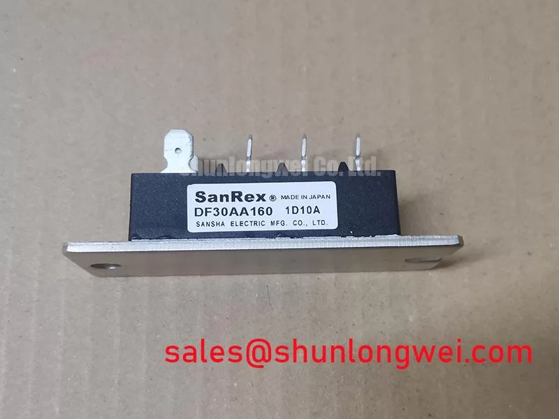
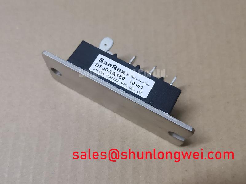
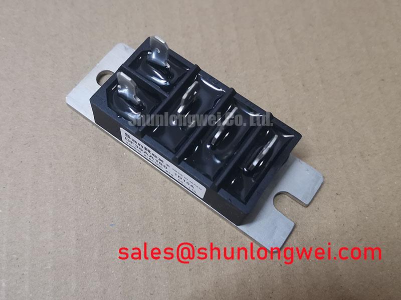
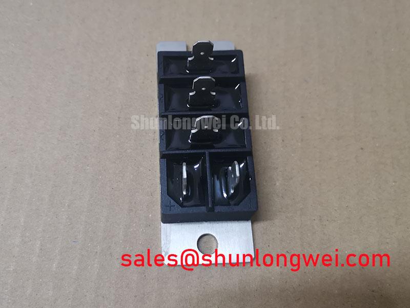
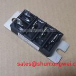
DF30AA160 | SanRex (Sansha Electric) | Three-phase bridge rectifier | 1600 V rated voltage (Official Specification) | 30 A rated current (Official Specification) | SanRex Power Module package
Probe each AC terminal against both DC output terminals with a multimeter in diode mode, then reverse the leads and record the cold-state readings. This checks whether the terminal polarities follow the intended bridge path before the DF30AA160 is connected to an energized circuit. Compare the results with a known-good unit and the equipment schematic; a reading by itself does not establish the cause of a fault.
During a controlled commutation test, capture current and voltage at the module terminals together. Reverse recovery peak current and recovery time affect switching stress, but neither value is established by the supplied 1600 V and 30 A ratings. An observed current spike therefore needs to be assessed against the actual circuit, operating temperature and applicable manufacturer data rather than assigned an assumed device limit. Where an active front end is being reviewed, the Vienna rectifier topology provides useful circuit context; it does not define the connections or behavior of this bridge module.
For a replacement assessment, match the terminal map, package mounting interface and electrical duty first. The CVM50BB160 is a separate SanRex reference for comparing system-level ratings, not a drop-in substitute for a three-phase bridge rectifier.
DF30AA160 Snubber Checks on the Bench
Capture the voltage across the bridge and the current through its AC feed when a switching event produces ringing. Note whether the oscillation coincides with commutation, upstream switching or another event before changing the protection network. RC snubber resistance and capacitance are system choices: designers should tune them against the measured waveform, component dissipation and the 1600 V module rating. No snubber values or reverse-recovery limits are specified here.
A series reactor may be evaluated where measured current rise calls for additional control, provided its effect on normal operation is checked in the assembled circuit. Keep the measurement reference and probe layout consistent between captures so that a change in test setup is not mistaken for an improvement. In equipment that also contains a controlled switching stage, Miller charge, active clamping and gate behavior belong to that stage’s device and driver assessment; they are not DF30AA160 gate specifications. An MDS500-12 may appear elsewhere in a power-conversion assembly, but its role and ratings require a separate schematic comparison.
💡 Bench Tip: Discharge and isolate the power stage before diode-mode testing, and keep the probe polarity and cold-state reference consistent across all bridge paths.
DF30AA160 AC Input Surge Protection Assessment
Measure the surge-related voltage at the AC input and at the bridge terminals, rather than assuming an input protection device limits both points equally. Lead layout and the placement of a metal oxide varistor or RC stage can change the stress seen by the module. As a Design Consideration, select and validate those parts against the equipment’s defined surge environment and measured terminal waveform; the rectifier’s 1600 V rating alone is not an equipment surge-immunity claim.
Use the applicable IEC 61000-4-5 test plan when surge immunity is an equipment requirement. The standard concerns the system test, not an independent certification of this rectifier. Record the test configuration and inspect bridge paths again after testing so a changed diode-mode reading can be investigated alongside the waveform evidence.
Short-circuit protection needs the same circuit-level discipline. Compare the prospective fault current and the semiconductor fuse’s clearing I²t with the rectifier’s documented surge and I²t limits under the relevant conditions. No DF30AA160 fuse coordination table, mounting torque or terminal assignment is provided in the stated specifications, so none can be inferred from the package name.
DF30AA160 AC-to-DC Transfer and Reliability Checks
Trace the bridge’s DC output back to its three AC inputs when the measured bus voltage disagrees with the equipment drawing. Check phase presence, diode paths and loading before attributing the discrepancy to the rectifier. The DF30AA160 is identified here as a three-phase bridge rectifier; firing-angle control belongs to a separately identified controlled-rectifier stage. Applying thyristor firing-angle behavior to this module would give an unsupported transfer characteristic.
In a grid-tied static var compensator or thyristor-switched capacitor assembly, engineers may assess this bridge for an auxiliary AC-to-DC function if the schematic, terminals and operating duty agree. Harmonics and reactive-power behavior must be evaluated at the equipment level, particularly where a controlled stage shares the AC supply. The Power Electronics Masterclass offers broader context for documenting power-stage tests, while MTBF terminology is useful when reviewing reliability claims. Neither supplies a measured service life or failure rate for this module.