

Content last revised on September 19, 2026
Preventing Spurious Faults: Reverse Recovery Charge Guidelines for SBA500AA160
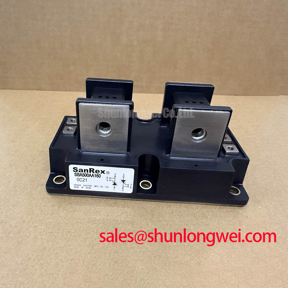
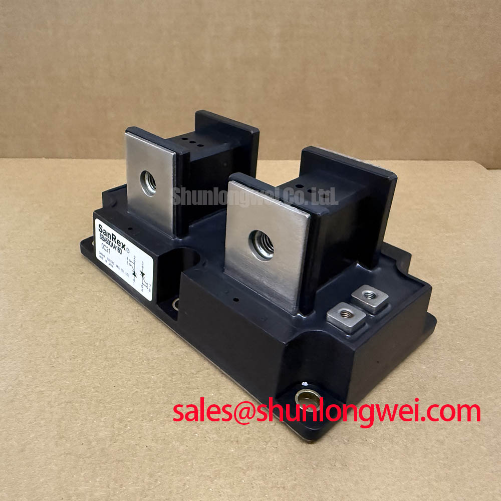
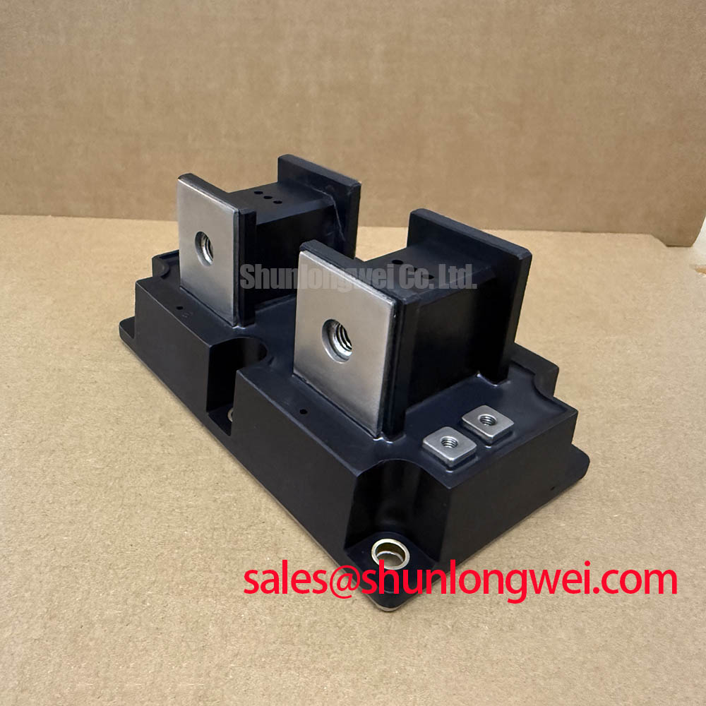
Before installation, verify the nameplate against the required voltage and current boundary, inspect the power terminals and insulating surfaces, and compare the replacement device with the original circuit position. The SBA500AA160 is a SanRex (Sansha Electric) thyristor and diode module specified for high-current power conversion equipment, including evaluation in medium-frequency induction melting and metal hardening power supplies.
| Parameter | Symbol | Official Specification | Conditions |
|---|---|---|---|
| Repetitive Peak Off-State Voltage | VDRM | 1600 V | Official datasheet specification |
| Repetitive Peak Reverse Voltage | VRRM | 1600 V | Official datasheet specification |
| Isolation Voltage | VISO | 2500 V RMS | AC, 1 minute |
| Average On-State Current | IT(AV) | 500 A | Tc = 66 °C |
| Surge On-State Current | ITSM | 10000 A | 60 Hz, half-sine wave, non-repetitive |
| Peak On-State Voltage | VTM | 1.45 V | IT = 1500 A |
| Thermal Resistance | Rth(j-c) | 0.085 K/W | Junction to case |
| Junction Temperature Range | Tj | −40 to +125 °C | Official datasheet specification |
These values identify the electrical boundary of the device, but they do not replace the original equipment manufacturer’s firing circuit, fuse coordination data, cooling arrangement, or insulation procedure. The listed 500 A average on-state current is specified at a case temperature of 66 °C; the actual permissible current in a furnace power converter remains dependent on the complete thermal path, current waveform, duty cycle, cooling method, and enclosure conditions.
When evaluating the SBA500AA160 in a commutation leg, begin with the actual current path rather than assuming that a replacement module will reproduce the switching waveform of a different device. Confirm the terminal identification from the original SanRex documentation and the equipment schematic, then inspect the busbar joints, clamping surfaces, and return path before applying power. The factory information supplied for this product confirms the voltage ratings, current ratings, isolation rating, on-state voltage, and thermal resistance listed above. It does not provide reverse-recovery charge, reverse-recovery peak current, or reverse-recovery time in the supplied parameter set, so those values should be verified from the applicable manufacturer data before detailed switching-loss calculations.
Design Consideration: Reverse-recovery behavior can influence commutation stress, transient voltage, conducted noise, and the heating distribution between parallel or complementary switching paths. A suitable evaluation uses the installed line and load conditions, the actual firing angle, the complete commutation network, and oscilloscope measurements taken at the semiconductor terminals. Designers should assess the recovery waveform together with the surge suppressor and fuse response rather than treating the 1.45 V peak on-state voltage specification as a switching-loss value.
For an induction melting or hardening supply, inspect whether the replacement occupies a rectifier position, controlled rectifier position, or a commutation position. The related PK55FG120 may be evaluated as a neutral reference for an associated rectification stage, subject to voltage, current, terminal, mechanical, and control compatibility checks. This is a comparison point, not a guaranteed substitute for the SBA500AA160.
Fuse selection must be based on the equipment manufacturer’s coordination table, the prospective fault current, clearing time, and the semiconductor’s documented short-duration withstand data. The supplied SBA500AA160 information includes a non-repetitive 10000 A surge on-state current rating at 60 Hz with a half-sine waveform. That rating should not be interpreted as a permitted repetitive operating current or as a complete fuse I2t coordination value.
⚠️ Field Alert: Do not insert or remove power connections while the furnace converter is energized; isolate the supply, verify the discharge state, and follow the equipment’s lockout procedure before handling the module.
Assembly Integrity & Layout Architecture: Preventing Localized Gate Hotspot Burnout for SBA500AA160
Check the firing interface, gate wiring, and cathode reference at the module terminals before attempting a live firing test. The supplied factory data does not specify gate pulse current, gate pulse rise time, holding current, or a multi-pulse firing requirement for this exact model. Those control values must therefore come from the applicable SanRex gate-drive documentation or the original equipment design. They should not be inferred from the 500 A average on-state current rating.
Engineering Recommendation: Keep the firing loop physically short, route the gate and return conductors as a close pair, and separate sensitive firing wiring from high di/dt power conductors where the equipment layout permits. The purpose is to reduce unwanted coupling and improve repeatable triggering. Final pulse amplitude, pulse duration, and timing should be verified at the device terminals under the installed temperature and operating-current conditions.
Uneven mechanical assembly can create a second source of abnormal heating. Clean the mounting contact area according to the equipment service procedure, confirm that the module sits flat, and ensure that the power connections are free from burrs, contamination, and mechanical strain. No model-specific mounting torque value is included in the supplied official parameter set, so the installer should use the SanRex mechanical drawing or the original assembly specification rather than applying an assumed torque.
The thermal boundary is clearly defined by the official Rth(j-c) of 0.085 K/W, measured from junction to case. This value describes the junction-to-case portion of the thermal path; it does not certify a complete heatsink, interface material, airflow, or liquid-cooling design. During commissioning, record case temperature at a known load and use the complete thermal model to assess junction temperature against the specified range of −40 to +125 °C. Temperature data should be interpreted together with current waveform, firing symmetry, and cooling performance.
For maintenance planning, document the original terminal arrangement, conductor orientation, insulating hardware, and trigger wiring before removal. If a same-family device is being considered for a service event, the FRS200CA100 can be reviewed as a separate SanRex product reference, but its ratings and physical compatibility must be independently verified for the target assembly.
SBA500AA160 Circuit Protection & Reliability: Evaluating Industrial Surge Immunity
Start a protection review at the incoming AC terminals and follow the complete path toward the thyristor and diode junctions. The SBA500AA160 has an official 1600 V VDRM repetitive peak off-state voltage rating and 1600 V VRRM repetitive peak reverse voltage rating. These are device ratings, not a declaration that a complete furnace power supply satisfies line-filter or EMC requirements, nor do they establish compliance with IEEE 61000-4-5 at system level.
Design Consideration: MOVs, RC snubbers, line reactors, filters, and fuses should be selected from the measured supply topology, prospective surge exposure, normal working voltage, energy duty, and required coordination. The protection network must limit the voltage and current reaching the semiconductor while avoiding unwanted leakage, excessive capacitor current, or interference with firing behavior. The system engineer should verify the resulting peak voltage at the module terminals during representative surge and switching tests.
The 2500 V RMS isolation specification for one minute is an official electrical isolation value for the module under its stated test condition. It should not be treated as a complete cabinet insulation or operator-protection certification. Creepage, clearance, pollution level, enclosure construction, cable routing, and the isolation of the control transformer or gate-drive supply remain system-level responsibilities.
When reviewing a medium-frequency induction power supply, inspect the relationship between the input rectifier, DC-link or intermediate circuit, inverter stage, and protective network. A surge suppressor placed far from the semiconductor may show an acceptable measurement at the cabinet entry while leaving the local commutation loop exposed to wiring inductance. Minimize the high-current protection loop and validate the result using measurements at the module terminals. The external reference on deep-level transient spectroscopy concerns semiconductor material analysis and should not be read as a qualification report for this SanRex product.
For long-term evaluation, record the operating case temperature, line condition, firing pattern, cooling state, and fault history. The technical article Unlocking Efficiency in Industrial Drives provides background on a different power-semiconductor technology; it is not a substitute for the SBA500AA160 datasheet or a thyristor-specific reliability qualification.
Preventing Spurious Faults: Short-Circuit Withstand Limits and Coordination Guidelines for SBA500AA160
During a short-circuit protection review, first identify the fault loop, the upstream protective device, and the point at which current is interrupted. The SBA500AA160 official data provides a 10000 A non-repetitive surge on-state current rating under a 60 Hz half-sine condition. This figure describes a defined surge test condition and does not by itself establish the permissible duration of a dead short, the fuse clearing energy, or safe operation under a high-frequency fault waveform.
Fuse coordination should use the semiconductor fuse manufacturer’s published clearing I2t, let-through current, pre-arcing behavior, and interruption characteristics together with the equipment short-circuit study. Compare those values against the applicable SanRex transient-current and thermal-limit data. Because the supplied product parameters do not include a semiconductor fuse I2t coordination table, no guaranteed fuse size or clearing interval can be stated for this model.
Engineering Recommendation: Test the protection chain under controlled conditions with the furnace power stage disabled from normal energy transfer and with appropriate measurement equipment. Confirm that the protective device interrupts the fault before the module exceeds its documented electrical and thermal limits. Review the busbar geometry, terminal tightness, insulation barriers, and contact resistance after testing, since a protection device may clear a fault while leaving mechanical or thermal damage that is not visible during the event.
After a suspected fault, compare the device’s off-state blocking behavior, terminal insulation condition, and firing response with a known-good test arrangement. A changed measurement may indicate damage in the module, wiring, gate circuit, snubber, or measurement setup; isolate each part of the path rather than assigning a single cause from one reading. Any replacement decision should also confirm the original voltage class, current duty, cooling interface, terminal arrangement, and control compatibility.
The specified junction temperature range of −40 to +125 °C provides an official temperature boundary for evaluation, while the 0.085 K/W junction-to-case thermal resistance helps define the thermal model. The final protection design remains dependent on the complete furnace converter, its fault energy, protective devices, mechanical installation, and verified test results.