

Content last revised on September 19, 2026
QM100HA-H Replacement Verification and Identification
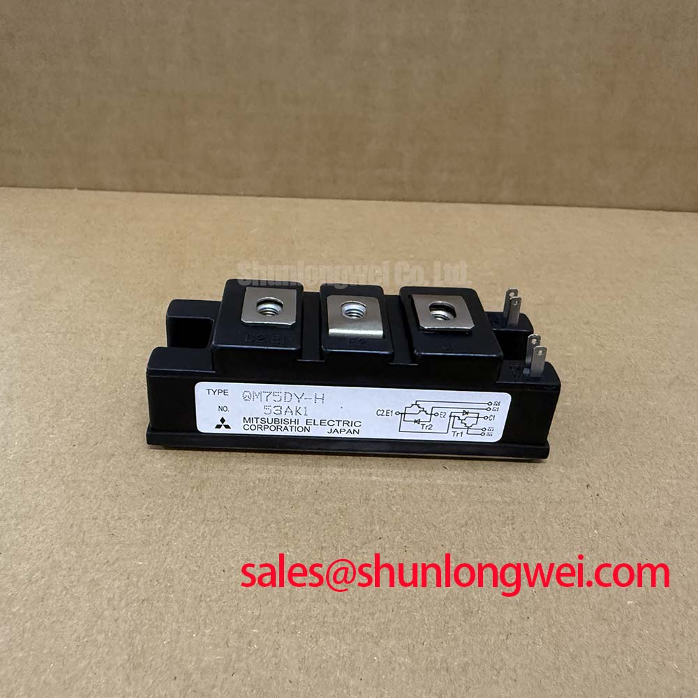
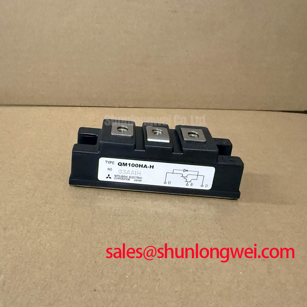
Before energizing a replacement drive, verify the nameplate against the control cabinet record, inspect the isolated mounting face for damage or contamination, and measure the removed power circuit for unintended low resistance paths. The QM100HA-H from Mitsubishi Electric is an Isolated Darlington Module rated at 600.0 V and 100.0 A as an Official Specification. These ratings establish the module identity, but the surrounding commutation circuit, base drive, cooling assembly, and protection thresholds must be verified from the original equipment documentation before installation.
| Parameter | Specified Value | Classification |
|---|---|---|
| Manufacturer | Mitsubishi Electric | Official Specification |
| Part number | QM100HA-H | Official Specification |
| Rated voltage | 600.0 V | Official Specification |
| Rated current | 100.0 A | Official Specification |
| Package type | Isolated Darlington Module | Official Specification |
For equipment repair teams assessing electric material handling or forklift traction controls, this module should be evaluated as a direct electrical and mechanical service item rather than by current rating alone. Confirm the original terminal assignment, control wiring polarity, heatsink contact area, bus arrangement, and the drive circuit condition. Mitsubishi Electric maintains technical information on power semiconductors and high power modules, which can support broader device family identification where the equipment documentation is incomplete.
Assembly Integrity and Layout Architecture for QM100HA-H Thermal Interface Control
Begin heatsink preparation with the removed module. Old thermal compound, embedded debris, corrosion residue, and raised burrs can prevent the QM100HA-H mounting surface from transferring heat evenly into the heatsink. Clean both faces using an approved process for the site, then inspect the contact pattern after a controlled trial fit. A contact mark concentrated at one edge may indicate heatsink distortion, uneven mounting pressure, or an unsuitable thermal interface layer.
A thermal interface material thickness of 50 to 100 μm is a Design Consideration for a properly prepared power module mounting interface, not an official QM100HA-H factory requirement. The objective is to fill microscopic surface irregularities without creating a thick insulating layer. The chosen material, dispenser method, mounting surface condition, and heatsink flatness determine the final result. Where the heatsink has minor curvature, the interface process should compensate without allowing voids to form beneath the module.
Install mounting fasteners in a progressive cross pattern so the module settles evenly across the thermal interface. The correct tightening torque, thread engagement, washer arrangement, and sequence must follow the host equipment service documentation or the approved fastener specification. Do not infer those values from another Mitsubishi Electric package. After the first controlled thermal run, inspect for grease displacement, movement at the mounting points, and discoloration around nearby insulation barriers.
⚠️ Maintenance Note: Monitor heatsink contact temperature trends and keep the cooling airflow path clear before a gradual temperature rise is mistaken for an electrical fault.
In a forklift or warehouse traction controller, dust accumulation and moisture cycling can affect cooling performance and terminal condition at the same time. During scheduled maintenance, check fan operation, clear the heatsink channels, examine thermal interface material for drying or pumping, and inspect power terminals for evidence of looseness or heat exposure. A measured rise in contact temperature may result from airflow restriction, degraded thermal contact, increased load duty, or a control problem, so it should be assessed with the full operating context.
QM100HA-H Thermal Electrical Optimization Through Return Path Separation
The QM100HA-H is a Darlington module, so its drive and return arrangement must be assessed from the original circuit rather than by applying IGBT gate drive assumptions. Confirm the actual control terminals and their reference path from the equipment schematic. In particular, the controller return should not be allowed to share a high current power path where load current can impose noise on the drive reference. This is a Design Consideration intended to reduce unintended switching disturbance and to make oscilloscope observations more representative of the device control signal.
Keep high current conductor routes compact and ensure the control wiring has a deliberate, low noise reference. The physical path matters: a return conductor routed alongside a noisy output bus can receive coupled disturbance even when the circuit diagram appears correct. When replacing a module in an existing drive, retain the original approved harness routing and terminal order unless the system design authority has issued a revision.
If unstable switching, excessive ringing, or irregular current waveforms are observed, inspect the full commutation path rather than assigning the condition to one component. The reverse recovery behavior of the applicable freewheeling diode can influence transient shape, but the diode arrangement for the specific equipment must be confirmed from its original documentation. Snubber parts, if present, should be checked for connection integrity, capacitance condition, resistor heat damage, and secure placement close to the intended commutation loop.
Engineers comparing controller repairs can review the QM100HY-2H as a related power semiconductor reference when examining associated rectifier or auxiliary power stages. It should not be treated as an automatic substitution for QM100HA-H because voltage class, current duty, terminal layout, control requirements, and circuit role must all be matched to the equipment design.
Benchtop Waveform Tuning and High Frequency Commutation Loop Control
Perform waveform checks with the module installed in its intended mechanical position and with measurement connections arranged to minimize probe induced error. A long ground lead can create a misleading ringing trace and lead to changes that do not solve the real issue. Compare the observed collector path voltage, load current, and drive command with a known healthy controller where one is available, using appropriate high voltage measurement practice.
The switching voltage transient follows the engineering relationship that peak voltage rises from the DC link voltage by an amount related to loop inductance and the rate of current change. This is an Engineering Calculation principle, not a fixed QM100HA-H limit. Reducing parasitic loop inductance helps suppress turn off overshoot, but the permitted peak voltage, switching transition rate, snubber requirement, and clamping response must be validated by the system engineer against the 600.0 V module rating and the actual transient measurement.
For practical layout work, use closely coupled outgoing and returning power conductors, preserve symmetrical bus geometry where the topology requires it, and avoid unnecessary conductor length between the module, DC link capacitors, and commutation components. Planar bus structures can reduce loop area when they are suitable for the enclosure, but no universal dimensional target should be copied into a repair job. Clearances, insulation coordination, mechanical restraint, and service access remain system determined requirements.
Snubber capacitor selection cannot be derived from module current rating alone. Its suitability depends on stored energy, switching frequency, commutation current, the measured ringing frequency, resistor dissipation, and the allowable stress on the surrounding circuit. Before changing a snubber network, verify whether the original fault is caused by poor capacitor connections, a changed load condition, incorrect control timing, or a power bus issue. For broader fault isolation and measurement discipline, consult the Field Engineer’s Handbook.
Overvoltage Trip Prevention During Regenerative Deceleration
During motor deceleration, a traction drive can return energy toward the DC link. The controller must manage that energy through the topology fitted by the equipment manufacturer, which can include controlled regeneration, a braking branch, or another system level method. The QM100HA-H rating alone does not define the correct braking strategy, trip threshold, resistor value, or braking transistor selection.
When investigating repeated overvoltage trips, first establish whether the event occurs during deceleration, load reversal, battery state changes, abnormal mechanical inertia, or an intermittent power connection. Confirm the DC link measurement method, inspect busbar and capacitor terminations, and review the controller event record if available. A trip may reflect normal protective action under changed operating conditions, a degraded braking path, incorrect control timing, or a measurement problem. The evidence should determine the repair scope.
Where a braking transistor and ballast resistor are part of the original controller design, verify their part identification, mounting integrity, electrical connections, and thermal condition against the equipment documentation. The resistor must dissipate regenerative energy safely within the system duty cycle, while the braking switch and its control path must respond according to the controller design. These are system level engineering requirements and should not be assigned fixed values from the QM100HA-H module specification.
For current capacity comparison during an approved equipment redesign review, the QM200HA-HK is a related Mitsubishi Electric Darlington module reference. Any comparison requires confirmation of electrical ratings, mechanical interface, terminal arrangement, thermal performance, drive compatibility, and the original control architecture. Additional manufacturer context is available through Mitsubishi Electric semiconductor device technologies.