


Content last revised on May 31, 2026
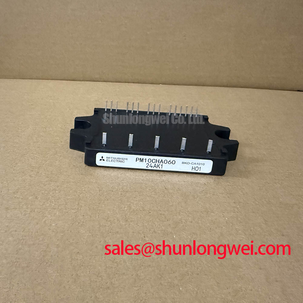
PM10CHA060: 600V / 10A Intelligent Power Module for Compact Motor Drives
Introduction and Key Features
Optimizing Low-Power Inverters with Integrated Protection and Control
The PM10CHA060 is a highly integrated Intelligent Power Module (IPM) designed to streamline the development of low-power three-phase motor control systems. This module combines six IGBTs in a three-phase bridge configuration with optimized gate drive and protection circuitry into a single, compact package. With core specifications of 600V | 10A | Tj(max) 125°C, it offers a robust solution for variable frequency drives and servo applications. Key engineering benefits include simplified PCB layout and built-in hardware protection. This IPM directly addresses the challenge of implementing reliable, space-efficient inverter stages in cost-sensitive applications. For applications requiring a higher current rating while maintaining the same voltage class, designers might consider the PM20CSJ060. Best fit for sub-1kW motor drives, its integrated design significantly reduces design complexity and time-to-market.
Application Scenarios & Value
System-Level Benefits in Compact Motion Control
The PM10CHA060 excels in applications where board space, component count, and reliability are primary design constraints. What is the main advantage of an IPM in small motor drives? It's the integration of gate drivers and protection circuits, which eliminates significant design effort and potential sources of failure. Consider a small-scale automated guided vehicle (AGV) or a conveyor belt system. The drive electronics must be compact and resilient. The PM10CHA060 provides a complete inverter power stage, including critical protection against short-circuit (SC), over-current (OC), and under-voltage (UV) events. This level of integration allows engineers to focus on motion control algorithms rather than the complexities of gate drive timing, shoot-through prevention, and fault handling, directly accelerating the development cycle for systems like commercial appliances, HVAC fan controllers, and small industrial servo drives.
Key Parameter Overview
Core Specifications for Inverter Design
The electrical characteristics of the PM10CHA060 are tailored for efficiency and reliability in low-power inverter applications. The following table groups key parameters by their functional area, providing a clear overview for system design and component evaluation.
| Parameter | Symbol | Conditions | Value | Unit |
|---|---|---|---|---|
| Absolute Maximum Ratings (Tj = 25°C) | ||||
| Collector-Emitter Voltage | VCES | - | 600 | V |
| Collector Current (DC) | IC | TC = 25°C | 10 | A |
| Collector Current (Peak) | ICP | Pulse Width < 1ms | 20 | A |
| Collector Power Dissipation | PC | TC = 25°C, per IGBT | 27.7 | W |
| Operating Junction Temperature | Tj | - | -20 to +125 | °C |
| Electrical Characteristics (Tj = 25°C, VCC = 15V) | ||||
| Collector-Emitter Saturation Voltage | VCE(sat) | IC = 10A | 2.6 (Typ) / 3.5 (Max) | V |
| FWDi Forward Voltage | VEC | IC = 10A | 2.5 (Typ) / 3.4 (Max) | V |
| Control & Protection | ||||
| Control Supply Voltage | VD | - | 13.5 - 16.5 | V |
| SC Protection Voltage | VCC(PROT) | VD = 13.5~16.5V | 400 | V |
Frequently Asked Questions (FAQ)
What is the primary benefit of the integrated fault output (Fo) signal in the PM10CHA060?
The Fo signal provides a direct, low-latency communication channel to the system's microcontroller (MCU). When the IPM detects a short-circuit, over-current, or under-voltage condition, it pulls the Fo pin low. This allows the MCU to immediately initiate a controlled shutdown of the system, preventing catastrophic failure and improving overall system safety without requiring complex external monitoring circuits.
How does the VCE(sat) of 2.6V (Typ) affect the thermal design for a 10A application?
The Collector-Emitter Saturation Voltage, or VCE(sat), is a critical parameter for calculating conduction losses. At a typical VCE(sat) of 2.6V and a collector current of 10A, the conduction loss per IGBT would be approximately 26W (P_loss = VCE(sat) * IC). This figure is the starting point for thermal calculations, directly influencing the required heatsink size and airflow needed to keep the module's junction temperature within its safe operating limits, especially under continuous load conditions in a compact Variable Frequency Drive (VFD) enclosure.
A Closer Look at Integrated Protections
Enhancing System Robustness Through On-Chip Safeguards
A key engineering advantage of the PM10CHA060 lies in its comprehensive, built-in protection features. These are not merely add-ons but are integral to the module's design, offering a level of coordinated protection that is difficult to achieve with discrete components. The short-circuit (SC) protection, for instance, is designed to detect a dangerous current spike and safely shut down the IGBTs within microseconds, a response time crucial for preventing device destruction. Similarly, the control circuit's under-voltage (UV) lockout ensures that the IGBTs are not driven with insufficient gate voltage, a condition that could lead to increased power dissipation and thermal runaway. By integrating these critical safeguards, the PM10CHA060 offloads the burden of protection circuit design from the engineer, ensuring a consistent and reliable level of safety across all manufactured units.
For engineers evaluating power solutions, our team is available to provide further technical details and sourcing information. Please contact us to discuss your specific application requirements for the PM10CHA060.