Content last revised on October 16, 2026
Preventing Spurious Faults: Harmonic Current Injection and Line Filter Guidelines for RBS80670XX
- Record the cold-state terminal condition before energizing the rectifier cabinet.
- Inspect the baseplate, heatsink contact area, fasteners, and thermal interface material.
- Confirm gate-drive isolation, terminal identification, and protection interlocks against the approved circuit drawing.
- Check the selected semiconductor fuse and its coordination data before any controlled power test.
| Product parameter | Listed information |
|---|---|
| Manufacturer | Powerex |
| Model | RBS80670XX |
| Voltage rating | Verify against the applicable manufacturer documentation. |
| Listed current rating | 800.0 A; applicable rating conditions must be verified in the manufacturer documentation. |
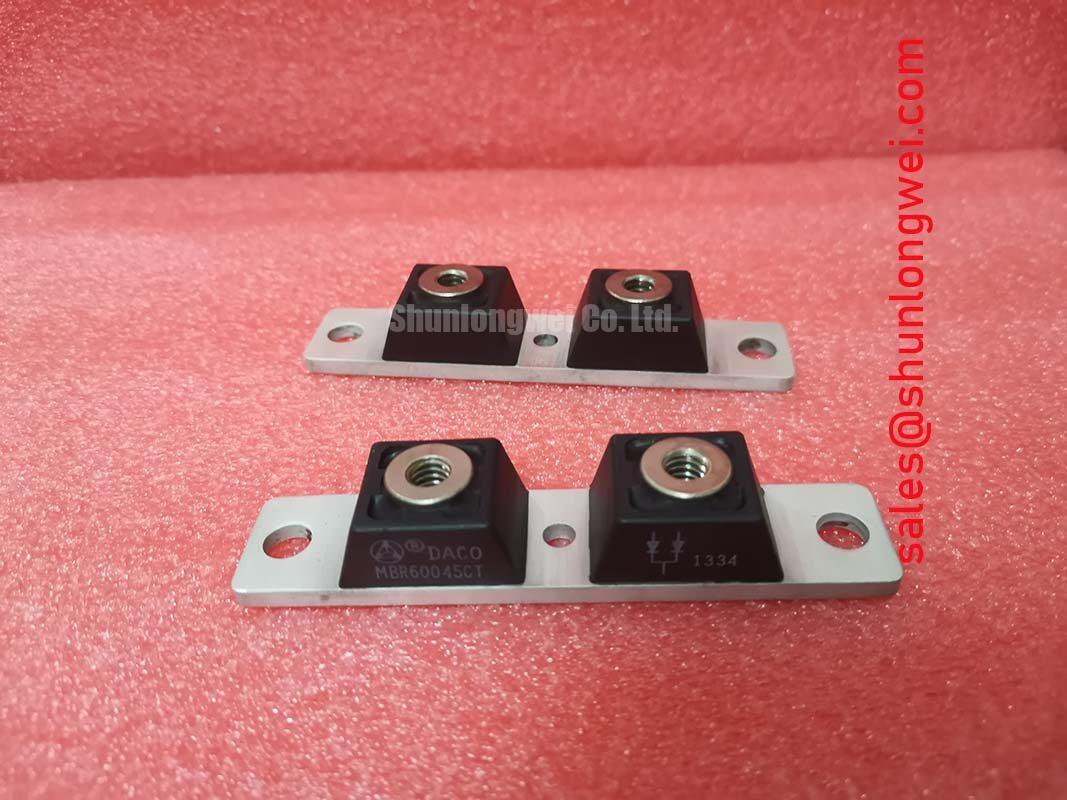
| Package | POW-R-BLOK |
For a controlled rectifier using the RBS80670XX, firing-angle management should be reviewed together with line impedance, transformer behavior, and the installed filter network. Within the operating range supported by the rectifier design, early firing supports higher conversion output, while later firing can worsen displacement power factor. The resulting current waveform should be assessed at the point of common coupling rather than inferred from the module current rating alone.
Design Consideration: harmonic current suppression is a system function. Engineers should compare phase current, displacement power factor, and reactive power at several commanded firing angles while the rectifier is connected to its actual transformer and load. A filter selected without considering source impedance can shift distortion into another operating region. For a high-current green hydrogen electrolyzer DC power rectifier, the line filter, transformer, control loop, and semiconductor bridge should therefore be evaluated as one electrical network.
Terminal connections require a clean mechanical path with no looseness, damaged lugs, or unplanned parallel current routes. The approved assembly drawing should control terminal identification and tightening torque. The listing identifies the package as POW-R-BLOK and the current rating as 800.0 A; the applicable rating conditions and device voltage rating must be verified before selecting the fuse and terminal hardware for the system. Reference information on high-power semiconductor modules is available from Powerex High Power Semiconductor Modules.
Transient Dynamics & Electrical Design: Ensuring Uniform Heatsink Contact Pressure on RBS80670XX
Thermal verification begins at the baseplate and heatsink interface. Remove old interface material, inspect the mating surfaces for burrs or contamination, and confirm that the heatsink is flat enough for the specified assembly method. Apply the approved thermal interface material consistently; excessive compound can reduce mechanical stability, while insufficient coverage can leave localized thermal paths.
The overall junction-to-ambient thermal path must be evaluated with the installed heatsink, airflow, ambient temperature, and load profile. The package should sit naturally on the heatsink before fasteners are tightened. Cross-tightening in a controlled sequence helps distribute pressure, but the permitted torque must come from the applicable Powerex mechanical documentation rather than from a generic value for another package.
After assembly, inspect the interface for evidence of rocking, uneven squeeze-out, or baseplate distortion. Measure temperature at comparable operating points and compare phase positions within the rectifier. A rising temperature difference between positions may justify checking airflow balance, terminal resistance, compound condition, or mounting pressure before replacing the module.
⚠️ Maintenance Note: Schedule heatsink cleaning and thermal-interface inspection with the plant preventive-maintenance plan, and trend contact temperature after reassembly.
In cabinets exposed to humidity or rapid temperature changes, allow the assembly to reach a stable condition before high-current operation. Condensation control, enclosure sealing, and airflow filtration are installation responsibilities. The RBS80670XX should be evaluated for the intended electrolyzer rectifier duty only after these environmental and thermal conditions have been verified.
Benchtop Waveform Tuning: Mitigating Stress Through Short-Circuit Coordination on RBS80670XX
Short-circuit coordination must start with the semiconductor fuse clearing characteristic and the device withstand data applicable to the installed circuit. The required comparison is between the fuse total clearing I²t and the thyristor or diode I²t limit specified for the matching operating condition. Peak let-through current and device voltage limits must also be checked. A fuse label alone is not enough to establish protection performance.
Use the manufacturer’s coordination table where available, then check the actual fuse part number, prospective fault current, source impedance, and wiring inductance. The objective is to limit semiconductor stress during a sub-cycle fault, but no bench procedure can convert an unverified fuse combination into a guaranteed zero-damage result. Any protection claim should be supported by the relevant Powerex application data and the fuse manufacturer’s published curves.
Gate triggering also deserves attention during waveform tuning. IGT and VGT values must be taken from the applicable device data, while the gate-drive circuit should be checked for pulse amplitude, pulse width, isolation, return-path integrity, and susceptibility to common-mode transients. A pulse train can be considered when the controller and device documentation support it; the final trigger pattern is determined by the gate-drive design and commutation behavior.
For bridge controls that include firing interlocks, verify that they prevent invalid firing sequences while allowing the commutation sequence required by the topology. Keep the gate-drive loop compact and verify the gate-to-cathode waveform at the module terminals, not only at the driver output. Current-sense placement can affect the protection response; application guidance on shunt monitoring and current-sense amplifiers is available from Texas Instruments.
When evaluating rectifier architectures for high-power charging or electrolysis systems, the related engineering discussion in The Race for Efficiency provides useful system-level context. During the bench test, capture firing-angle command, bridge current, line voltage, gate waveform, and protective trip timing together so that a transient can be correlated with the complete control sequence.