


Content last revised on September 12, 2026
Assembly Integrity & Layout Architecture: Preventing Localized Gate Hotspot Burnout for RM1800HE-34S
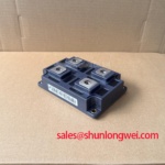
| Manufacturer | Mitsubishi |
|---|---|
| Part Number | RM1800HE-34S |
| Category | Thyristor/Diode Module |
| Package | Isolated Module |
| Topology | General Power Stage |
| Series | Standard |
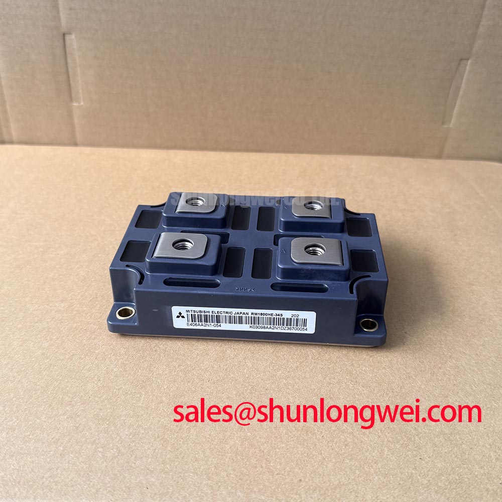
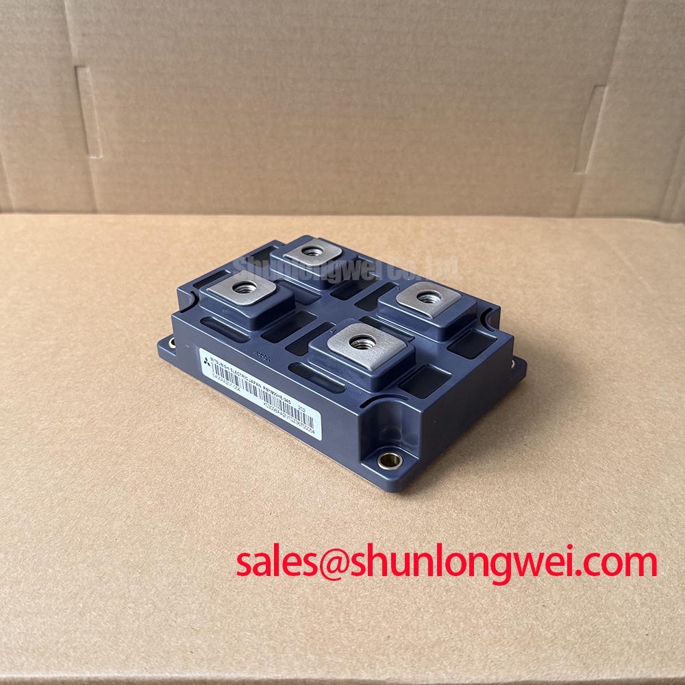
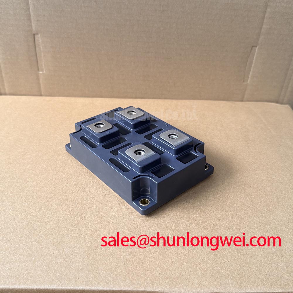
Trace every control and power terminal from the original equipment wiring diagram to the installed RM1800HE-34S before reconnecting a firing circuit, because the supplied official product data identifies the unit as a thyristor/diode module but does not define its internal terminal arrangement or gate characteristics. A continuity check alone cannot establish terminal function in a multi-terminal isolated power module.
Use the original equipment documentation to identify whether the assembly contains controlled thyristor paths, diode paths, or externally driven firing connections. Then compare each terminal location, cable lug orientation, and busbar contact surface against the removed unit. A firing pulse with poor rise behavior, incomplete holding support, or an incorrectly routed return path can create uneven current initiation in a controlled power stage. This is a Design Consideration, not an official electrical rating for this part number.
For a high-voltage three-phase motor solid-state soft starter, the firing transformer, isolated driver, and control return wiring should be checked as a complete signal path. Inspect for loose terminal hardware, damaged insulation sleeves, carbon tracking, or control cables routed tightly alongside high-current conductors. These conditions can affect pulse integrity and may produce inconsistent phase conduction during a starting sequence.
💡 Bench Tip: Keep the module disconnected from the energized power circuit while recording cold-state diode-mode readings, then compare like-for-like terminal paths with the original circuit drawing or a known-good assembly.
Where a repair bill of materials includes another controlled power-semiconductor position, the TD25N12KOF can be reviewed as a separate device option only after its topology, terminal layout, voltage rating, current rating, and mechanical interface have been verified against the equipment requirements.
RM1800HE-34S Circuit Protection & Reliability: Calibrating Mechanical Mounting Torque Sequence and Thermal Contact
Inspect the heatsink contact face for burrs, old compound ridges, corrosion, and local distortion before placing the isolated module onto the cooling surface. Uneven contact can concentrate thermal loading at part of the baseplate, while excessive or uneven clamping force can mechanically stress the package.
Apply thermal interface material as a thin, continuous layer using the equipment manufacturer’s service procedure, then tighten mounting hardware in an alternating pattern across the baseplate. The required fastening torque, screw size, tightening order, and interface material are system-dependent unless they are specified in the original Mitsubishi documentation for the installed assembly. This is an Engineering Recommendation intended to promote uniform pressure rather than a factory torque specification for RM1800HE-34S.
After final tightening, inspect the module perimeter and terminal plane for rocking or visible package distortion. Recheck busbar alignment without forcing the main terminals sideways. A busbar that reaches the terminal only under mechanical tension can transfer vibration and thermal expansion forces into the module connection.
Protection coordination should remain tied to the actual starter schematic. The fuse, contactor, bypass path, snubber network, and control interlock together determine the fault response. For related front-end power positions, engineers may compare connection and application requirements with devices such as the SKKT-106B16E, while treating it as a separate component requiring independent electrical verification.
Field Diagnostics & Commissioning: I²t Sub-Cycle Fuse Coordination for RM1800HE-34S Topologies
Measure diode-mode behavior between the identified power terminals with the module isolated from surrounding circuits, because parallel snubbers, resistors, transformers, and semiconductor paths can otherwise alter the reading. Record the meter polarity, terminal pair, and observed forward or blocked response rather than assigning a pass or fail result from a single generic voltage value.
A forward response in one direction and a blocked response in the opposite direction can be consistent with a diode path, but the expected terminal matrix must come from the original circuit documentation. Unexpected low resistance in both directions, open behavior where a documented diode path should exist, or a reading that changes after removing connected wiring may indicate a condition requiring further circuit-level isolation.
For dead-short fault analysis, semiconductor fuse selection requires coordination between the fuse manufacturer’s published pre-arcing and clearing I²t information and the withstand capability stated in the applicable module documentation. The fuse I²t is an energy-related integral of current over time; it cannot be compared responsibly without the actual fault current, clearing curve, source impedance, and device withstand data. This is a Design Consideration for the complete soft-starter assembly.
During commissioning, capture phase current symmetry, line voltage, firing reference timing, and bypass-contactor transition behavior. An abnormal current pattern can arise from several locations, including a firing channel, a line-side connection, a protection component, or the power module itself. Practical fault-prevention methods and broader device-selection context are discussed in Future of Power Electronics.
Preventing Spurious Faults: Coordination of Primary Spark Gaps, MOVs, Guidelines for RM1800HE-34S
Check the incoming protection assembly for cracked MOV bodies, heat-darkened terminals, loose surge-protection wiring, and snubber capacitors with signs of mechanical damage before returning the soft starter to service. These components influence transient stress at the power-stage terminals, particularly where long feeder cables, switching contactors, or transformer-fed supplies are present.
MOVs, spark gaps, RC snubbers, and line-side suppression elements must be assessed against the actual supply architecture and the equipment’s approved surge-protection design. Their placement and ratings are determined by the AC source, contactor behavior, cable inductance, expected transient environment, and measured peak voltage conditions. Do not transfer values from another starter frame or voltage class without confirming the complete protection network.
Use oscilloscope measurements with appropriately rated probes to compare firing timing and transient behavior among the three phases during controlled testing. A spurious trip or uneven startup may indicate a timing reference issue, noise coupling, degraded suppression hardware, or an impedance difference in the power path. Verify observations against the known-good signal path and the equipment schematic.
For general reference on Mitsubishi power-device families and their application categories, consult the Mitsubishi Electric Diode Modules Lineup and Mitsubishi Electric High-Voltage HVIGBT Modules. These references support family-level comparison and do not replace the original equipment documentation for the RM1800HE-34S installation.