Content last revised on October 12, 2026
Transient Dynamics and Electrical Design for Gate Trigger Current and Temperature Dependence
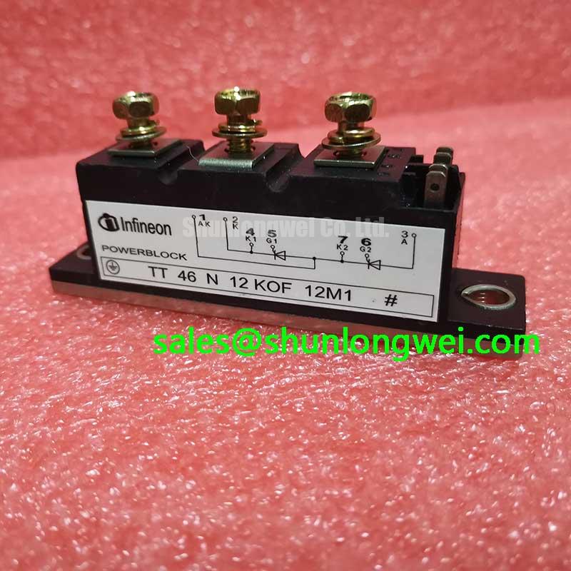
When a high current rectifier shows uneven phase conduction, inspect the firing pulse at the module gate terminals while comparing all bridge legs under the same operating condition. The TD25N12KOF is an Infineon Thyristor/Diode Module with an official voltage rating of 1200 V and an official current rating of 25 A, housed in a PowerBlock Module package. These ratings define the component identity, but the complete firing circuit still determines gate current, pulse shape, thermal behavior, and commutation stress.
For commissioning, confirm terminal identification against the applicable device documentation before applying a trigger signal. Record the gate pulse rise time, pulse width, and gate-current profile, along with phase-to-phase timing. A multi-pulse firing scheme can be considered where the controller must maintain reliable triggering across temperature and load changes. The firing circuit should prevent excessive repeated gate drive or localized heating by coordinating pulse energy with the thyristor gate requirements specified for the actual production lot.
Fuse coordination belongs to the complete rectifier design. Select protection by comparing the semiconductor fault withstand information, fuse clearing behavior, and the system short circuit level rather than assigning a generic fuse from the nominal current alone. The same approach applies to MOV protection: the clamping network should be coordinated with the AC line, commutation transient, and the module voltage boundary. Verify the resulting peak voltage at the power terminals during controlled switching tests.
Gate loop routing should remain short and arranged symmetrically between corresponding bridge arms. Minimize parasitic inductance in the trigger return path and keep high di/dt power conductors away from sensitive firing references. The system designer should also review the isolation and common mode transient performance of the industrial drive board. Infineon’s information on Intelligent Power Modules provides useful system context, although the TD25N12KOF itself should be evaluated according to its own device documentation.
Benchtop Waveform Tuning for Six Pulse and Twelve Pulse Bridge Configurations
In a six pulse rectifier, capture the three phase firing sequence and compare conduction symmetry between the positive and negative bridge groups. For a twelve pulse arrangement, examine the phase displacement produced by the transformer arrangement and confirm that the interphase transformer shares current as intended. A mismatch in trigger timing, transformer leakage, or wiring resistance can shift current into one bridge group even when the controller commands equal firing angles.
For a high current green hydrogen electrolyzer DC power rectifier, the bench setup should reproduce the intended transformer secondary connection, interphase transformer connection, DC smoothing network, and firing controller interface. Evaluate the waveform at light load before increasing current. Check that each gate trigger pulse is present at the intended firing instant and that commutation does not create an abnormal voltage excursion at the module terminals.
Firing angle adjustment changes the rectifier’s average DC output, reactive power demand, and harmonic profile. Testing across the planned control range, including late firing operation approaching 150 degrees where applicable to the topology, allows engineers to observe the transition from useful power conversion to unstable or poorly utilized operation. The controller should be tuned from measured bridge behavior, not from a nominal angle assumption.
For twelve pulse equipment, compare the current in each secondary and each bridge before finalizing the interphase transformer design. Harmonic reduction depends on transformer phase relationship, source impedance, load balance, and firing control accuracy. If the upstream architecture includes a separate rectifier stage, the DD1200S33K2C may be reviewed as a neutral reference for a complementary circuit stage, subject to electrical and mechanical compatibility checks.
Assembly Integrity and Layout Architecture for Power Factor and Harmonic Mitigation
Inspect the PowerBlock mounting surface, terminal hardware, conductor seating, and thermal interface before energizing the bridge. The manufacturer’s official mechanical installation data, including the applicable mounting torque and terminal tightening requirements, should control the assembly procedure. Do not substitute a general fastener value for the device specific instruction.
Power factor degradation in a phase controlled rectifier is associated with firing angle, current waveform distortion, commutation overlap, and the upstream source impedance. Harmonic mitigation may involve transformer phase shifting, line reactors, passive filtering, active compensation, or a combination selected by the system designer. Each option should be evaluated with the actual electrolyzer load profile and the grid connection requirements.
High voltage assembly also requires a physical review of creepage distance, clearance, contamination level, enclosure conditions, and conductor routing. MOVs, fuses, and snubber networks must be positioned so that their connection inductance does not undermine transient protection. Any insulation coordination or EMC claim belongs to the complete assembled equipment; the discrete module itself should not be described as independently certified for an entire installation.
💡 Pro Tip: De energize the rectifier and verify the absence of stored DC voltage before touching gate wiring, MOV networks, or bridge terminals.
For detailed gate loop layout principles, engineers can consult Precision Gate Drive Design. When comparing a different current class or voltage class, review the electrical ratings, terminal geometry, trigger requirements, and thermal interface independently; the TT92N14KOF should be treated as a separate candidate for documented compatibility assessment rather than an automatic substitute.