
Content last revised on October 27, 2026
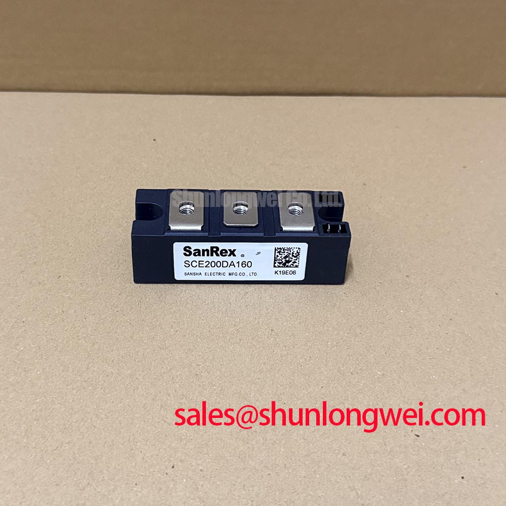
SCE200DA160 Incoming Inspection and Installation Checks
- Isolate the power stage, verify that stored energy has been discharged, and record cold terminal resistance before applying any gate signal.
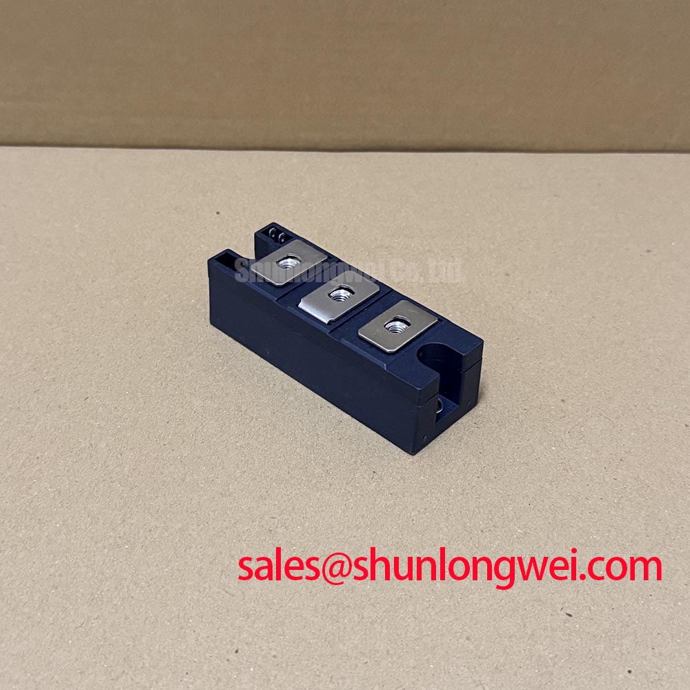
- Confirm the terminal markings against the original schematic and inspect the baseplate, mounting surface, and fastener condition.
- Check driver isolation, gate wiring continuity, and the insulation condition between the control circuit and power circuit.
- Check the system fuse against the module’s applicable surge-current and I²t data.
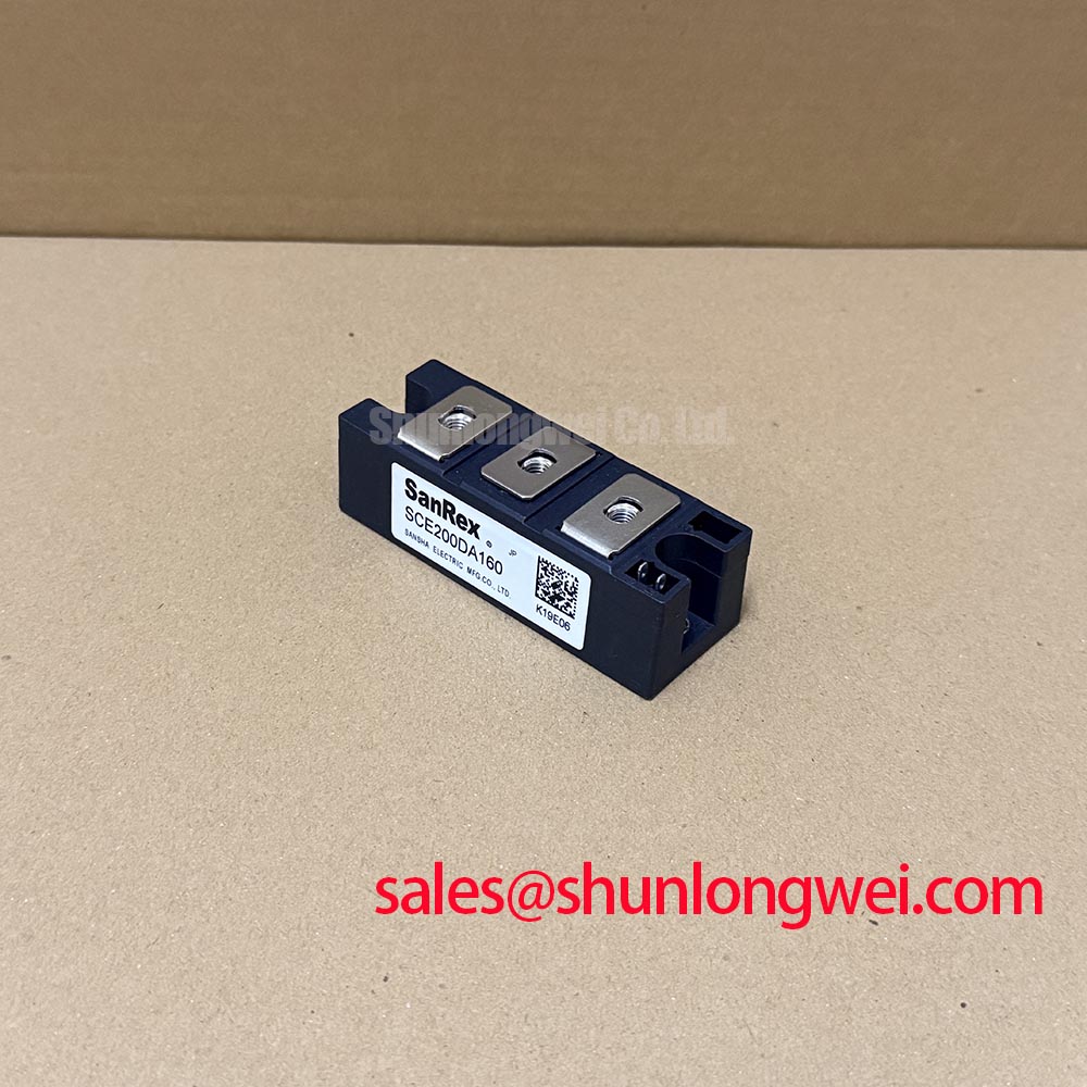
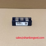
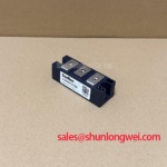
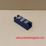
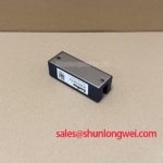
SCE200DA160 is a SanRex (Sansha Electric) thyristor and diode power module for industrial power conversion assemblies. Confirm its exact voltage and current ratings, internal circuit configuration, and rating conditions in the applicable manufacturer documentation. The original equipment drawing should also be checked when evaluating a repair or replacement.
For incoming inspection, use the same meter range, lead polarity, and discharge condition for every comparison unit. A cold-state reading across the principal terminals can reveal an unexpected short, but a high resistance reading alone does not establish an open-circuit failure or semiconductor health. The gate and auxiliary terminals should be checked against the equipment schematic rather than inferred from physical position. Designers evaluating a replacement in an induction power supply should also compare terminal geometry, creepage arrangement, fuse coordination, and cooling hardware before energizing the assembly.
💡 Bench Tip: Keep the device in an ESD-controlled work area and record a known-good cold-state baseline before comparing a returned module.
Benchtop Waveform Tuning: AC-to-DC Transfer Characteristics across SCE200DA160
When the module is used in a phase-controlled AC-to-DC stage, vary the firing angle within the converter’s approved operating range while monitoring the DC output, line current shape, power factor, and reactive power demand. In rectifying operation, increasing the firing angle generally delays conduction and reduces the average DC output voltage; the exact relationship depends on the circuit and load. The test record should therefore contain the commanded angle, measured DC output, RMS line current, and the operating load for every point.
Do not judge the firing circuit from the controller command alone. Confirm that the gate pulse reaches the correct terminal with the intended polarity and that the pulse remains present at the actual module terminal after cable and isolation-stage effects. In a medium-frequency induction melting or hardening furnace, the upstream transformer, commutation network, and load power factor can materially alter the current waveform seen by the module. The system engineer should verify peak current and voltage margins during controlled switching tests rather than assign a universal operating limit from the module name alone.
Fuse selection belongs beside the waveform record. Compare the protective device clearing characteristic and I²t capability with the semiconductor protection data specified for the equipment design. A fuse that interrupts quickly but does not coordinate with the module can still expose the power stage to damaging energy. For neutral technical comparison, the PDMB 200E6 may be reviewed as a related power-module reference, while its electrical and mechanical data must be checked independently.
Use the Mitsubishi Electric Diode Modules Lineup as an industry reference for comparing diode-module terminology and protection concepts; it does not establish specifications for the SanRex device. For a replacement evaluation, confirm that the original control board, snubber network, fuse, and heat-transfer path are compatible with the SCE200DA160 installation.
SCE200DA160 Circuit Protection and Reliability: Mechanical Torque and Thermal Contact
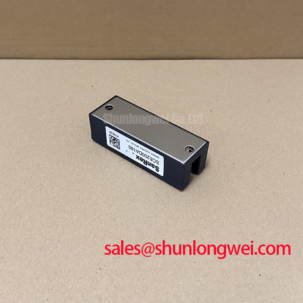
Thermal performance begins with uniform contact between the module baseplate and the heatsink. Remove old compound, inspect both mating surfaces for burrs or contamination, and apply the approved thermal interface material as a thin, even film. The purpose is to eliminate air gaps without creating hydraulic pressure that can distort the package during tightening.
Use the mechanical drawing for the applicable mounting-hole pattern, fastener type, washer arrangement, and torque value. Tighten progressively in the specified sequence so that the baseplate seats evenly; the final torque is a manufacturer or equipment-design requirement, not a generic value that can be transferred from another module. After assembly, inspect for rocking, visible package stress, or displaced compound around the baseplate. The thermal path should then be checked under the intended load while monitoring heatsink temperature and current balance where applicable.
In a furnace inverter or rectifier cabinet, the thermal assessment should include airflow, heatsink orientation, neighboring busbars, and the duty cycle of the load. A baseplate may be mechanically secure while still showing poor thermal contact if the mating surface is uneven. Designers should verify the measured temperature rise against the system thermal model and the applicable SCE200DA160 documentation, especially where repeated heating cycles increase thermal cycling.
Preventing Spurious Faults: High-di/dt Gate Firing and Pulse-Train Timing
Gate firing should be assessed at the module terminals, not only at the output of the driver board. The oscilloscope record should show gate-to-cathode voltage, gate current, pulse width, repetition pattern, and the relationship between the command pulse and main-terminal current. Select gate-current rise time and pulse amplitude using the applicable manufacturer guidance, while observing the gate limits and permissible main-current rate of rise.
A pulse train can improve firing consistency when the first pulse encounters changing noise or supply conditions, yet excessive pulse energy or poor return-path layout can increase localized gate stress. Keep the gate loop compact, separate the control return from high-current commutation paths, and verify isolation-device common-mode transient behavior during the same switching event. The driver should be checked for pulse loss, ringing, and timing displacement when the power circuit carries load current.
Commutation overshoot is strongly affected by busbar geometry and stray inductance. Minimize the high-current commutation loop and verify measured peak voltages against the applicable device ratings and system limits during switching tests. A conventional thyristor is not turned off by removing or reversing its gate drive; the circuit must provide suitable current commutation and recovery time. The engineering guide Evolution of Negative Off-Bias Gate Drive Circuits provides broader context for other gate-drive arrangements, but it does not establish a suitable bias scheme for this module. Any bias arrangement must be checked against the actual SanRex gate-drive requirements.
When a pulse-train test produces an intermittent fault, compare the gate waveform at the driver, isolation barrier output, and module terminal in sequence. This separates control timing, common-mode coupling, wiring inductance, and module-terminal issues without assigning a single cause from the fault symptom alone.