Shunlongwei Co. ltd.
IGBT Module / LCD Display Distributor
Customer Service
+86-755-8273 2562
IGBT Module / LCD Display Distributor
“Infrared remote control uses infrared (IR) light to transmit information. The modulation signal of the transmitter MCU controls the IR LED to emit infrared light. Modulation can help the receiver distinguish the desired signal from all other sources of infrared noise. The realization process of modulation is to modulate the carrier signal (usually a square wave with a higher frequency) with an envelope signal with effective information.
“
Infrared remote control uses infrared (IR) light to transmit information. The modulation signal of the transmitter MCU controls the IR LED to emit infrared light. Modulation can help the receiver distinguish the desired signal from all other sources of infrared noise. The realization process of modulation is to modulate the carrier signal (usually a square wave with a higher frequency) with an envelope signal with effective information.
The receiver uses photodiodes to convert IR light into current. Usually a transimpedance amplifier is used to convert the current into a voltage; before demodulation, the voltage will pass through a gain amplifier and filter. The carrier signal is removed during the demodulation process. The demodulated signal can be directly connected to the receiver’s MCU for decoding.
Infrared remote control modulation and coding theory
All new infrared remote control designs adopt digital modulation. The two basic digital modulation techniques are amplitude shift keying (ASK) and frequency shift keying (FSK). ASK expresses logic 1 and 0 by changing the carrier amplitude, while FSK uses two different carrier frequencies to express these logic levels.
ASK modulation
ASK is one of the oldest and simplest technologies, and is favored by many consumer electronics companies. With its excellent performance (good robustness and low power consumption), simple design and low cost, it has become the most popular modulation mode.
In the transmitter, the valid data is modulated into a set of carrier pulses with a frequency ranging from 30kHz to 60kHz. When there is no signal transmission, an empty number is inserted.
The receiver is tuned to the same frequency as the transmitter carrier, and all other noise is blocked by the receiver’s bandpass filter. Many manufacturers provide fully integrated receiver Modules that provide demodulated signals that interface with the receiver microcontroller. The typical carrier frequency is 30kHz, 33kHz, 36kHz, 38kHz, 40kHz or 56kHz.
Several main coding methods used in the ASK modulation system will be explained below.
● Pulse position coding Pulse position coding is basic ASK modulation. Each bit width is constant. The carrier modulated pulse represents logic 1, and the space sign represents logic 0.
● Pulse distance coding In pulse distance coding, each bit is composed of a carrier modulated pulse and a space number. The width of the empty number is used to distinguish between logic 1 and logic 0. The pulse width of the carrier modulation is constant.
● Pulse width coding In pulse width coding, each bit is composed of a carrier modulated pulse and a space. Carrier modulation pulse width is used to distinguish between logic 1 and logic 0, and the space number is constant.
● Manchester encoding Manchester encoding is also called bi-phase encoding. Each bit consists of a carrier modulation pulse and a space number. The polarity of the transition between the carrier modulated pulse and the space sign dictates the logic level. For example, “modulated pulse to space” means logic 1, and “space to modulated pulse” means logic 0.
FSK modulation
FSK uses two different carrier frequencies for logic 1 and logic 0, and there is no space between pulses. This solution uses two frequencies, increasing the complexity and cost of demodulation, so it has not been widely used.
Overview of MSP430FR4xx
MSP430FR4xx is a member of the ultra-low-power MSP430 series of 16-bit microcontrollers. It has optimized peripheral resources and IR modulation logic, making it very suitable for remote control applications. The powerful LCD Display function and abundant capacitive touch I/O resources expand its use in other fields such as blood pressure monitors, water meters, and dynamic tokens (OTP).
MSP430FR4xx infrared remote control realization
Infrared modulation is traditionally implemented mainly by software and limited hardware resources (that is, a timer is used to generate precise time slots). Because the time slot is small, the software overhead is high. MSP430FR4xx has some internal interconnection hardware resources (such as timer and SPI), so it can realize IR modulation with lower software overhead.
The IR modulation logic in MSP430FR4xx includes two cascaded timers and additional combinational logic (see Figure 1).
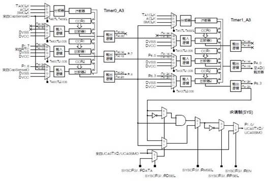
Figure 1: IR modulation logic Circuit.
IR modulation logic can be enabled by setting the IREN bit in the SYSCFG1 register. This logic has two different PWM input signals (derived from TA0 and TA1) to support ASK or FSK modulation. In ASK modulation, the first PWM from TA0 is used for carrier generation, and the second PWM from TA1 or the output from eUSCI_A can be used to generate the envelope. In FSK modulation, two PWM signals represent two different carrier frequencies. The IRMSEL bit in the SYSCFG1 register specifies the modulation mode. Before outputting to an external pin, the polarity of the modulation signal can be reversed by setting the IRPSEL bit in the SYSCFG1 register to adapt to different external drive Circuits.
The envelope waveform generation can be realized by hardware or software. In hardware mode, the envelope signal comes from TA1 (only available for ASK) or eUSCI_A. When it comes from the latter, it works in SPI mode, and 8-bit data is automatically sent serially. In software mode, the IRDATA bit in the SYSCFG1 register is responsible for controlling whether to send logic 0 or logic 1. The IRDSEL bit in the SYSCFG1 register is used to select whether to use the hardware mode or the software mode.
Modulation scheme
● ASK modulation IRMSEL bit defaults to ASK modulation. Modulate the two inputs of the AND gate to drive external LEDs: one is the carrier signal from TA0, and the other is the envelope timing signal from TA1, eUSCI_A or IRDATA bits. If it comes from the IRDATA bit, you need to use another independent counter (TA1, RTC or WDT) to periodically update this bit.
● FSK modulation If the IRMSEL bit is set, the FSK mode is enabled. TA0 and TA1 respectively generate two separate carrier frequencies. The envelope waveform can be generated by the eUSCI_A or IRDATA bit; if it is generated by the IRDATA bit, another independent counter (RTC or WDT) needs to be used to periodically update this bit.
Carrier generation
The timer is used to generate the carrier. Both TA0 and TA1 can be obtained from high-frequency SMCLK to achieve higher resolution and wider frequency range. The timer counter can work in “up” or “up/down” counting mode. The CCR0 is used to control the carrier cycle, and CCR2 is used to determine the duty cycle of the carrier. From a system perspective, a smaller duty cycle helps reduce power consumption. The typical duty cycle is about 3/16 to 4/16. Up to 7 output modes can realize flexible carrier generation. After starting the carrier generation, the user does not need to update its configuration before the data transmission of one frame is completed.
Waveform envelope generation
The envelope waveform is determined by the data sent and the encoding method used. Users can use TA1, eUSCI_A or IRDATA to generate envelope waveforms according to the selected modulation mode.
When TA1 is used in FSK modulation, CCR0 is used to set the period of the envelope, and CCR2 is used to set the duty cycle. Therefore, for different encoding methods, CCR0 should be configured as 1 or 2 times the width of each bit; CCR2 must be updated before sending the next bit. The number of bits to be sent determines the number of interrupts that need to be triggered in a transmission, so it can be directly added to the software overhead and current consumption.
When using eUSCI_A in SPI mode, its baud rate should be configured to be 1 or 2 times the effective data baud rate. For example, in pulse position encoding, the same baud rate is configured, but in Manchester encoding, it needs to be doubled. Using SPI can greatly reduce the number of interrupts, thereby reducing software overhead.
When using IRDATA, another independent counter (usually RTC) is needed to update the IRDATA bit.
Hardware and software overhead considerations
The MSP-430 series is specifically designed for ultra-low power consumption applications to extend battery life. The highest principle to reduce power consumption is to increase the time in low power consumption modes (such as LPM0/LPM3) as much as possible. It is strongly recommended to use low-power integrated peripheral modules to replace the functions implemented by software. Due to carrier generation, high frequency SMCLK is indispensable. During IR data transmission, in terms of modulation and coding mode, the time in LPM0 mode should be extended as much as possible. From this perspective, eUSCI_A is the most desirable because it can get the longest time slot (4 or 8 bits). However, in some applications that need to use eUSCI_A to perform other tasks, other hardware resources such as TA1 and RTC should be used instead.
Protocol example
There are many infrared transmission protocols used in the industry, but most of them are developed from several basic protocols with different frequencies or formats. The “Pulse Distance Protocol” and “Manchester Protocol (RC5)”, which are the most popular protocols, will be explained below.
Pulse distance protocol
The pulse distance protocol is widely used by many home appliance companies. It uses ASK modulation and pulse distance coding with a carrier frequency of 38kHz.
● Frame format There are two types of frames in the protocol: data frame and retransmission frame.
The data frame consists of a pilot code and data. The pilot code is a burst of 9ms in length, followed by a pause of 4.5ms. The data payload includes an 8-bit address for identifying the device and an 8-bit command for the control word. To ensure reliability, both are sent twice. The second transmission of the address and the command is complementary, so the total length of the data frame is constant (67.5ms). The payload ends with a 560μs carrier modulated tail pulse to complete the final data gap. Logic 1 is defined as a 560μs carrier modulation period following the 1690μs space period. Logic 0 is defined as a 560μs carrier modulation period following a 560μs space period. Figure 2 shows a complete data frame format.
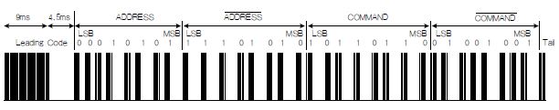
Figure 2: Pulse distance protocol, data frame format.
The retransmission frame is defined to handle the automatic retransmission function; it does not carry any address or command information. It consists of a sequence pulse and a trailing pulse following it. While the same key is still pressed, the retransmission frame is retransmitted every 110ms. The complete sequence format of the pulse distance protocol is shown in Figure 3.
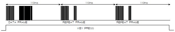
Figure 3: Pulse distance protocol, complete sequence format.
● Envelope generation If TA1 is used to generate the envelope waveform, CCR0 and CCR2 must be updated once for each pair of carrier modulated pulse and space. CCR0 depends on the carrier modulation pulse period and space period, while CCR2 depends on the carrier modulation pulse period. For example, if TA1 is provided by 4MHz SMCLK and uses the default divider configuration, CCR0 and CCR2 are configured to 54000 and 36000 respectively to generate pilot codes (9ms carrier modulation pulse is paired with 4.5ms space number), and the Logic 1 was updated to 9000 and 2240, respectively. To send a complete data frame, CCR0 and CCR2 must be updated 34 (1+8×2+8×2+1) times, which is implemented in the TA1 interrupt routine.
If SPI is used to generate the envelope waveform, its baud rate should be set equal to the minimum time slot of 0.56ms. Therefore, TXBUF should send 3 bytes of data (0xFF, 0xFF, 0x00) to transmit the pilot code, and the transmission of other bytes depends on the payload. Each data frame has 16 “1”s and 16 “0”s in total. The TXBUF of SPI needs to be updated about 15 (121/8) times, which is implemented in the SPI interrupt service routine. The software overhead is half of TA1 overhead.
● Carrier generation To generate a 38kHz carrier with a 1/4 duty cycle, it is necessary to configure CCR0 and CCR2 of TA0 according to SMCLK. For example, when using 4MHz SMCLK, CCR0 and CCR2 are configured as 105 (4000/38) and 26 (4000/38/4), respectively.
Manchester code (RC5)
The RC5 protocol was launched by Philips. It uses ASK modulation and Manchester encoding with a carrier frequency fixed at 36kHz.
● Frame format RC5 data frame starts with two logic 1 start bits (S1 and S2), followed by a flip bit (T), and the payload contains a 5-bit address and a 6-bit command. The flip position changes its value every time a new key is pressed. The 5 address bits are used to identify the device to be controlled, and the 6 command bits contain the information to be transmitted.
Logic 1 is defined as a 889 μs space period following the 889 μs carrier modulation pulse period. Logic 0 is defined as a 889 μs carrier modulation pulse period following the 889 μs space period.
The complete data frame has a fixed length of 24.9ms, and its format is shown in Figure 4.
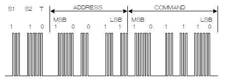
Figure 4: RC5 protocol, data frame format.
The automatic retransmission function is processed by retransmitting the data frame with the same flipped bit. In the extended version of RC5, the S2 start bit is interpreted as an inverted sixth address bit instead of a fixed logic 1.
● The minimum time slot for envelope generation is 889μs. The output mode of TA1 needs to be updated to generate the envelope waveform. For example, TA1 is provided by 4MHz SMCLK, and CCR0 and CCR2 are fixed to 7112 (2×889/0.25) and 3556 (889/0.25) respectively. The TA1 output mode needs to be updated at most 14 (3+5+6) times in each data frame, which is processed in the TA1 interrupt service routine.
If SPI is used, use the 889μs cycle to set the baud rate. Its TXBUF needs to be written about 4 (2×14/8) times to transmit a data frame, which can be handled in the SPI interrupt program.
● Carrier generation If you want to generate a 36kHz carrier with 1/3 duty cycle, configure CCR0 and CCR2 of TA0 according to the frequency of SMCLK. For example, when using 4MHz SMCLK, CCR0 and CCR2 are configured as 111 (4000/36) and 37 (4000/36/3) respectively. If SMCLK is 8MHz, the above two values should be doubled.
Software design and cost comparison
If there is no IR modulation logic circuit, it is usually necessary to use a timer to complete infrared transmission by controlling its PWM output. The counter cycle and channel duty cycle are consistent with the carrier cycle and duty cycle. Therefore, the software updates its PWM output according to the overflow count of the timer. For example, in the process of generating the pilot code of the pulse distance protocol, the software counts 342 (9ms/(1/38kHz)) times to overflow to output a 9ms carrier pulse, and counts 171 (4.5ms/(1/38kHz)) times to overflow to output. Space number of 4.5ms. During the overflow period, the device remains in LPM0 mode to save power. The frame length determines the number of wakeups.
In the case of the IR modulation logic circuit, the device only needs to wake up for a very limited time to achieve envelope generation, during which the carrier will be automatically generated without any intervention.
In order to better understand the superiority of the software overhead of the IR logic circuit during the transmission of a complete frame, here is a comparison of the number of interruptions using different methods for the pulse distance protocol and the Manchester protocol. See Table 1 for details.
Table 1: Comparison of software overhead for transmitting a complete data frame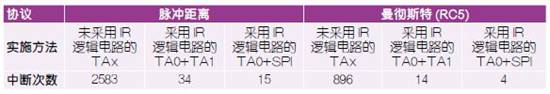
in conclusion
MSP430FR4xx devices include a wealth of peripherals and dedicated IR modulation logic function circuits, which can provide assistance for the development of infrared remote control implementation schemes that use ASK or FSK modulation. With TA0 and TA1, the carrier can be easily generated with almost no software intervention. The two typical examples given show that using eUSCI_A to achieve envelope generation can achieve the greatest reduction in software overhead.
The Links: NL6448BC20-12Y EVK71-050