




Content last revised on October 27, 2026
Field Diagnostics and Commissioning for Surge Protection
- Record cold-state resistance and continuity at every accessible power terminal before energization.
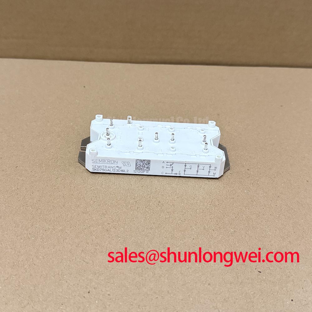
- Confirm the module marking, 1200.0 V voltage rating, 75.0 A current rating, and Semipont housing against the replacement record.
- Inspect heatsink flatness, contact coverage, terminal hardware, and conductor clearances before applying pressure or torque.
- Check gate or control circuit isolation where the surrounding rectifier uses controlled semiconductor switching.
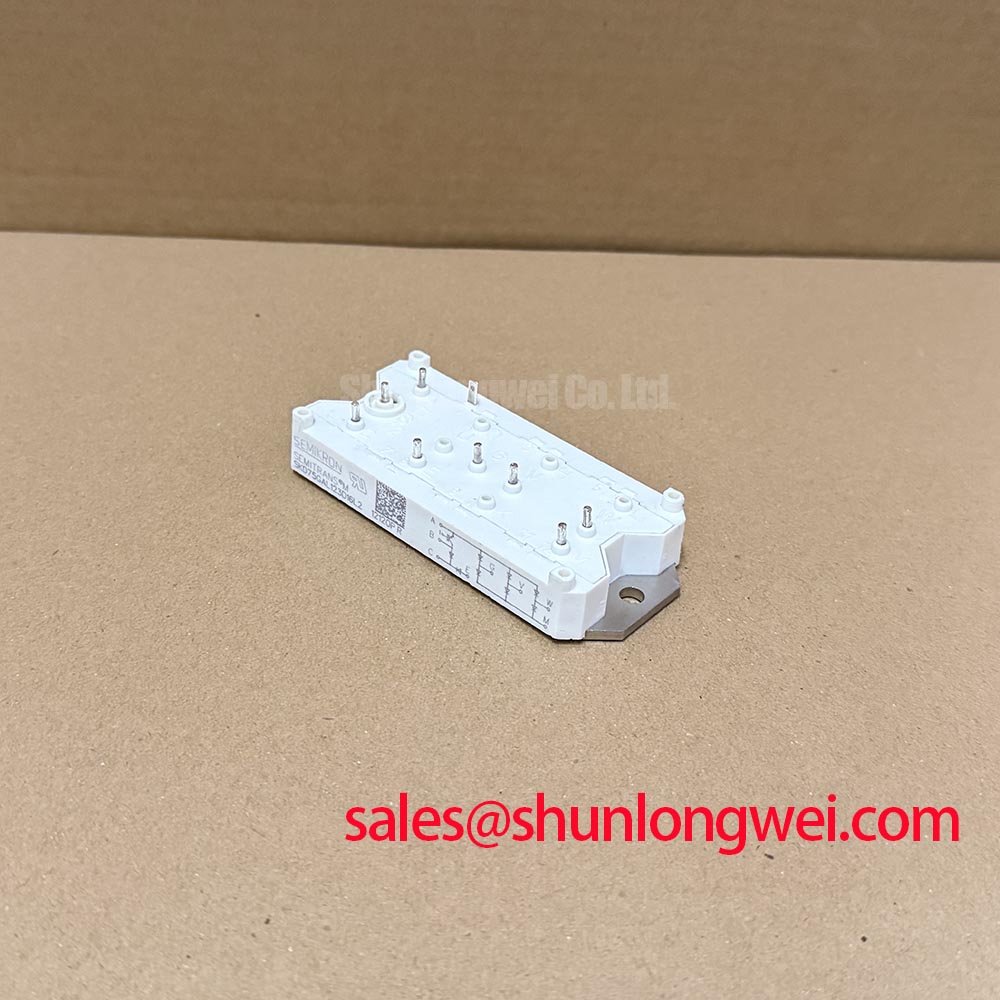
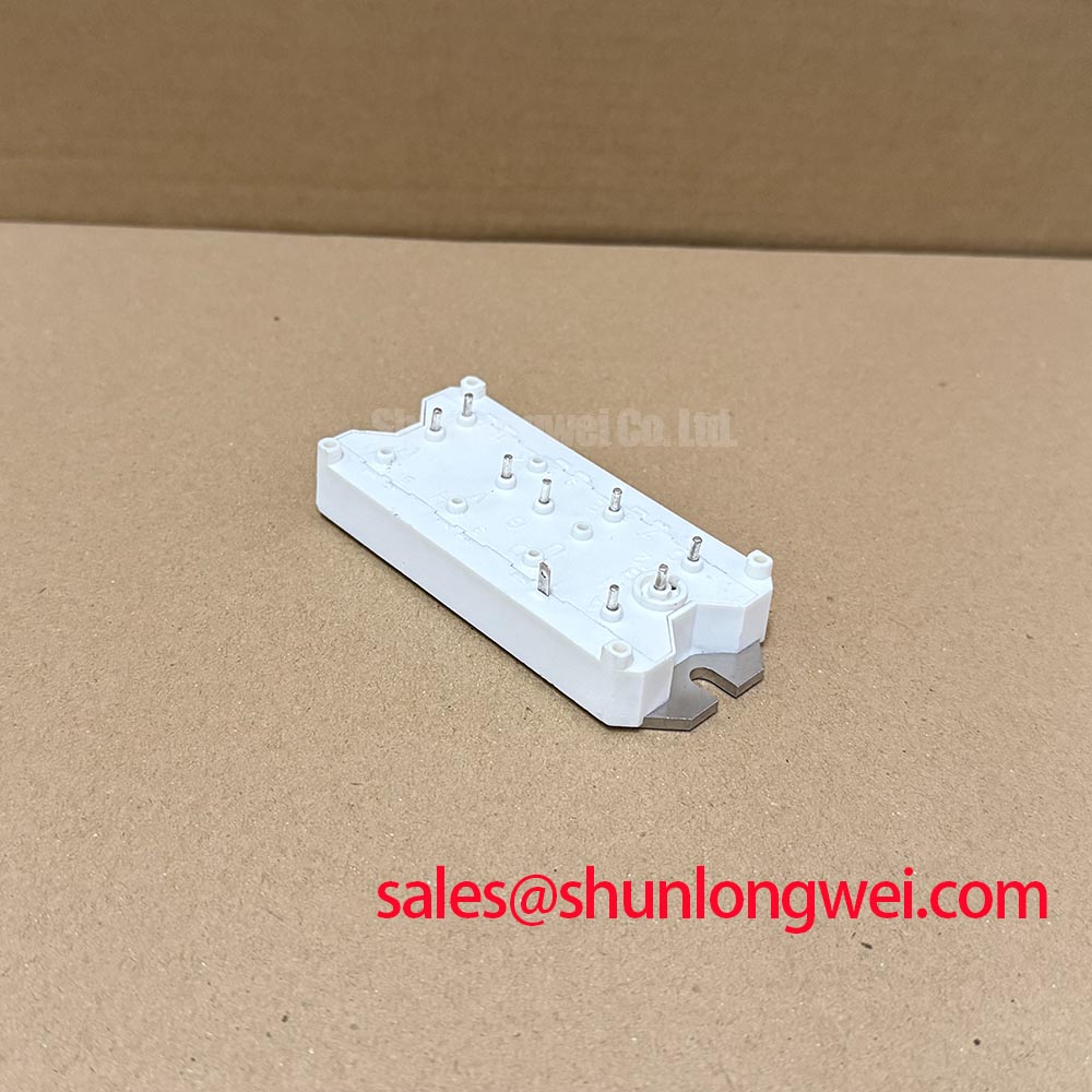
SKD75GAL123D16L2 is a Semikron bridge rectifier module specified at 1200.0 V and 75.0 A, with a Semipont housing. These are the confirmed product parameters for initial replacement screening. The complete electrical coordination still depends on the rectifier topology, semiconductor fuse, heatsink, control assembly, and operating waveform used in the equipment.
AC input protection should be checked as a complete network rather than as an isolated module accessory. In a high-current green hydrogen electrolyzer DC power rectifier, the incoming protection arrangement may include semiconductor fuses, metal oxide varistors, RC snubber stages, contactors, and a controlled rectifier section. The SKD75GAL123D16L2 rating provides the starting boundary for device selection, while the MOV working voltage and surge energy must be matched to the actual line-to-line and line-to-earth conditions.
For an IEEE 61000-4-5 evaluation, record the surge test configuration, coupling path, protective device location, and the voltage observed at the rectifier terminals. Passing a system-level surge test cannot be assigned to the bridge module alone. The surrounding protection must limit repetitive stress, avoid nuisance conduction, and prevent the protection network from transferring excessive energy into the semiconductor junctions.
When a thyristor-controlled front end is present, inspect the RC snubber connection directly at the relevant power terminals. A remote snubber can leave a substantial commutation loop between the suppression network and the junction. Verify terminal polarity, conductor identification, fuse placement, and the manufacturer’s specified mechanical tightening procedure. The fuse selection should be checked against the applicable clearing I²t and the module’s published surge-current data, rather than against the 75.0 A nameplate value alone.
Pro Tip: Keep the surge suppression and commutation paths physically compact and symmetrical, then verify terminal overshoot during controlled commissioning with an appropriately rated differential probe.
For the upstream or auxiliary rectification stage, engineers may evaluate the neutral reference and current-flow relationship with SKD116/18-L75. This is a separate component reference, not an automatic substitute for the SKD75GAL123D16L2.
Transient Dynamics and Baseplate Thermal Resistance
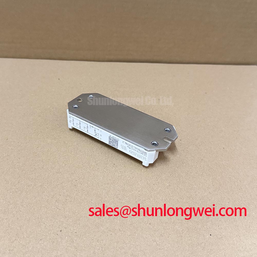
Thermal verification starts at the copper baseplate interface. The relevant junction-to-case thermal resistance, transient thermal impedance, allowable junction temperature, and pulse duration must come from the applicable Semikron documentation for the exact configuration. The confirmed listing parameters of 1200.0 V, 75.0 A, and Semipont housing do not by themselves define the heatsink requirement or short-duration thermal capability.
During assembly, inspect the heatsink surface for burrs, contamination, and local distortion. Apply thermal interface material as a continuous, controlled layer suitable for the mounting arrangement, then tighten the fasteners in a balanced sequence using the specified hardware procedure. Excessive localized pressure can distort the baseplate; insufficient pressure can leave air gaps and create a thermal path that changes under load.
Commissioning should compare the temperature rise at light load, rated operating conditions, and the highest expected rectifier duty. Use multiple measurement points across the heatsink to identify uneven spreading. If the measured temperature pattern changes sharply with current, review interface coverage, clamping uniformity, airflow, and the waveform’s conduction angle before attributing the result to the module.
In phase-controlled rectifiers, conduction angle affects both average output behavior and harmonic current. The control engineer should coordinate firing timing, line impedance, input reactor selection, and filtering with the electrolyzer power stage. The bridge module should not be presented as independently meeting a complete EMC requirement; the finished converter requires system-level evaluation. Engineering references from the Semikron-Danfoss Power Electronics and Modules Official Hub and the Semikron MiniSKiiP power module range can help frame the broader module and thermal-management context, while the exact product documentation remains controlling for this model.
Fuse I²t Coordination and Dead-Short Protection
Dead-short protection requires coordination between the semiconductor fuse clearing energy and the rectifier device’s documented withstand limits. Build the protection review from the selected fuse curve, prospective fault current, wiring impedance, DC-link capacitance, and the module’s published surge and short-duration ratings. A fuse with a suitable voltage class is not automatically coordinated with a 1200.0 V bridge module.
The engineering worksheet should record fuse pre-arcing I²t, total clearing I²t, peak let-through current, fault duration, and the applicable thyristor or diode withstand data. Compare those values under the actual supply impedance and connection arrangement. The result should be validated by the equipment protection study and controlled fault testing; a nameplate current of 75.0 A is not a dead-short clearing specification.
Where the surrounding driver uses desaturation monitoring, the protection sequence should identify the detection delay, gate shutdown behavior, soft turn-off strategy, and isolation barrier performance. The SKD75GAL123D16L2 product identity does not establish a built-in desaturation circuit. Designers should therefore verify whether protection is provided by the external driver and whether its common-mode transient immunity is compatible with the switching environment.
Minimize the high-current commutation loop to reduce transient voltage caused by stray inductance, and verify the peak voltage against the system DC-link boundary during switching tests. The engineering discussion at Stray Inductance, Transient Voltage Overshoot is relevant when reviewing busbar geometry, snubber placement, and probe connection. For replacement assessment, SKB52-08 may be reviewed as a separate bridge rectifier reference, but electrical, mechanical, thermal, and fuse-coordination compatibility must be established independently.