


Content last revised on September 29, 2026
Preventing Spurious Faults: Thermal Time Constants and Peak Junction Guidelines for SKIIP83ANB15T5
Capture the fault timestamp alongside phase current, heatsink temperature and load duration when a drive trips during a current pulse. A heatsink reading taken after shutdown can miss the junction temperature reached during the event: the semiconductor heats before that energy has fully moved through the package and into the heatsink. Compare the trip with a recorded normal operating cycle before treating a cool heatsink as evidence that temperature played no part.
The 83 A rating is an Official Specification, but it does not, by itself, establish an allowable overload duration. As a Design Consideration, estimate losses over the actual current waveform and apply the manufacturer’s transient thermal impedance data for the relevant heat path. For an isolated, approximately rectangular pulse, an Engineering Calculation can estimate junction temperature rise as pulse power multiplied by junction-to-case transient thermal impedance at the pulse duration. Repeated pulses require the temperature remaining from earlier events to be included; applying the isolated-pulse result to every cycle would understate the peak.
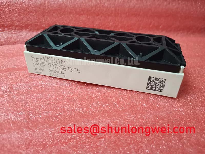
That calculation needs switching and conduction loss data, a defined case-temperature measurement point, and the applicable thermal impedance curve. The specified voltage and current alone cannot produce a defensible peak junction temperature or a permissible pulse limit. When comparing repair candidates, request the thermal data associated with the exact part designation rather than borrowing a curve from another package in the same product family. Semikron-Danfoss provides broader package context in its MiniSKiiP power module information; the assembled unit’s documentation remains necessary for a numerical thermal check.
If the trip follows rapid load changes, inspect the heatsink contact surface and record temperature close to the module during a controlled retest. Check whether cooling airflow, neighbouring heat sources or the drive’s current estimate changed between the reference cycle and the fault. A temperature-correlated trip may reflect thermal contact, cooling or loss calculation errors as well as the module itself. For a forklift traction-drive repair, treat this as a compatibility assessment: compare the original assembly’s mechanical interface, protection behaviour and duty cycle before evaluating SKIIP83ANB15T5 for that equipment.
Preventing Spurious Faults: Negative Gate Bias vs Active Miller Clamp Guidelines for SKIIP83ANB15T5
Probe the off-state gate voltage during the opposite switch’s transition and compare it with the driver’s commanded state. A brief gate excursion that coincides with a switching edge warrants investigation of the complete gate-return path, probe connection and driver behaviour; it does not establish cross-conduction on its own. Correlate that trace with collector current and the protection event, using measurement techniques appropriate to the energized power circuit.
As a Design Consideration, a low-impedance active Miller clamp or an appropriately controlled negative gate bias can help resist unintended turn-on during a high slew-rate transition. Neither approach should be assigned a bias setting from the 1500 V rating. The driver arrangement, device gate limits, clamp timing and behavior during supply loss must be checked against the original electrical documentation. If the assembly exposes a dedicated emitter-sense connection, route the driver return to that documented connection; do not infer that such a terminal exists from the package name. Keep the gate-drive loop compact and separate its return path from high-current conductors where the verified pinout permits.
Review the driver schematic as well as the gate waveform. A desaturation indication can result from a genuine overcurrent event, switching transients, sensing-path disturbance or a driver-supply problem. Check the sensing connection and blanking behaviour, then verify that the driver’s fault response and soft turn-off remain within the device’s documented short-circuit operating limits. No short-circuit withstand time or desaturation threshold is established by the three core specifications in the hardware card, so those values must come from the applicable device and driver records.
Other devices in the same equipment may affect the DC-link and protection sequence. For example, PM75CSD120 can be examined as a separate system-topology component when tracing supply and drive faults, not as an interchangeable unit or an assumed part of this module. The Precision Gate Drive Design guide provides further gate-loop design context. 💡 Pro Tip: Compare turn-off voltage overshoot with the DC-link voltage during a controlled switching test before deciding that a gate-drive change has improved the available margin.
Assembly Integrity & Layout Architecture: Optimizing Heatsink Contact Pressure for SKIIP83ANB15T5
Inspect the module-to-heatsink contact area for uneven compound transfer when a fault appears only after sustained loading. A local dry patch or excess compound is a reason to examine surface flatness, seating and assembly procedure, not proof of a particular internal defect. Record how the module was secured before removal so the reassembly can be compared with the original mechanical instructions.
As a Design Consideration, thermal interface material should form a continuous, controlled layer without using a thick deposit to conceal poor mating surfaces. Verify the approved material, application method, contact-pressure requirements and any mounting sequence for the actual MiniSKiiP / SKiiP assembly. A generic screw-torque figure is not a substitute for the specified fastening method, especially where module retention depends on an assembly-specific fixture. Where screws are used, bring the module into contact evenly and follow the documented sequence and torque for that hardware.
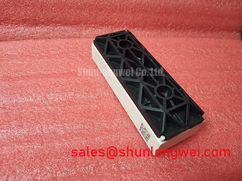
Check the mating surface for debris, raised edges and damage around mounting features. After assembly, compare temperatures at repeatable locations under a controlled load and look for a change from the reference unit. A warmer reading can also follow altered airflow or operating losses, so retain the electrical measurements alongside the thermal record. Semikron-Danfoss describes its broader SKiiP technology; mounting decisions still depend on the documentation for the installed configuration.
Layout inspection should cover conductor routing as well as heatsink contact. Keep the commutation path compact to limit turn-off inductive overshoot, then measure peak device voltage in the assembled system rather than assuming that physical proximity guarantees adequate margin. Preserve the original creepage and clearance scheme when replacing busbars, insulation pieces or adjacent hardware. The 1500 V Official Specification is a device rating, not a declaration of enclosure clearance or system insulation compliance.
For a maintenance comparison, SKIIP20NAC12IT2 is a separate Semikron part to assess against the original circuit records. Its different designation is not evidence of electrical, mechanical or protection compatibility with SKIIP83ANB15T5. Compare the documented pinout, ratings, mounting arrangement and driver requirements before considering any substitution.
Benchtop Waveform Tuning: Voltage Derating for SKIIP83ANB15T5
Measure the DC-link voltage and the highest turn-off voltage peak at the module during a controlled switching test. Compare the observed peak with the 1500 V Official Specification while checking the measurement bandwidth and probe placement. A clean-looking trace taken far from the module can hide a local transient; repeat the measurement at the relevant power terminals using the system’s approved high-voltage test procedure.
If the peak changes substantially with load or switching conditions, examine the commutation-loop layout, busbar connections and gate-drive behaviour together. As a Design Consideration, reducing loop inductance can reduce inductive overshoot, but the acceptable layout and operating margin are system-determined. Confirm them with measurements across the equipment’s intended operating conditions rather than prescribing a universal voltage derating.
Altitude and terrestrial radiation can be relevant to a system-level reliability review, but the stated specifications do not support a single-event burnout rate, failure-in-time estimate or altitude derating for SKIIP83ANB15T5. Do not turn a bench voltage trace into a lifetime prediction. If the equipment’s deployment conditions require that assessment, use applicable manufacturer reliability information and the installation’s defined environment; continue to address measured overvoltage through waveform verification and the documented device limits.