




Content last revised on October 1, 2026
SKKD-260-16 Operational Boundaries: Checking Surge and Reverse-Voltage Limits
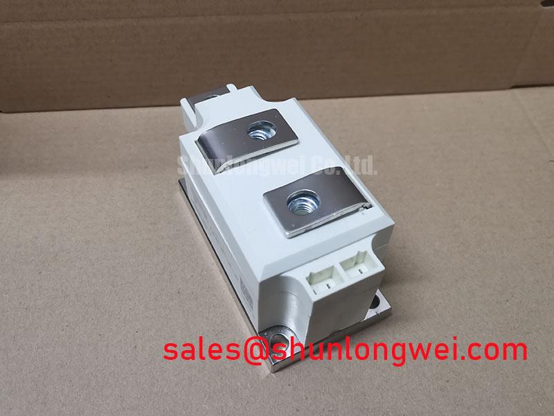
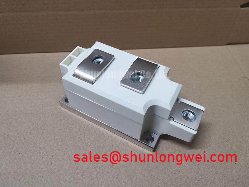
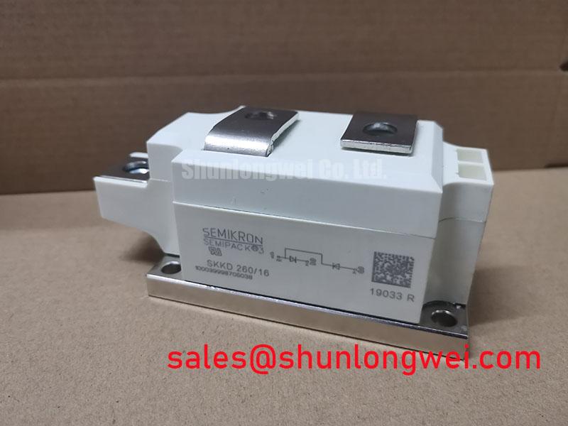
| Model | SKKD-260-16 |
| Manufacturer | Semikron |
| Product category | Diode module |
| Package | SEMIPACK |
| Supplied rating figures | 1600 V; 260 A. These figures require confirmation against the applicable manufacturer datasheet before use. |
Measure the isolated module’s diode paths in both directions and compare each reading with the circuit drawing and a known-good assembly. The SKKD-260-16 is a diode module: it has no gate connection, firing angle, or gate-pulse requirement. Its reverse-voltage duty depends on where each diode sits in the rectifier and on the voltage appearing across it during switching and faults.
The supplied 1600 V and 260 A figures should not be used to approve a repair until they match the applicable Semikron datasheet and the device marking. In particular, a continuous-current figure cannot establish a surge-current limit. For fuse coordination, compare the datasheet’s surge-current and I²t conditions with the selected semiconductor fuse’s clearing data. Account for the junction temperature at the start of a fault and allow for thermal recovery before reapplying reverse voltage. Neither the permissible recovery interval nor a mounting torque can be assigned from the supplied figures alone.
Assembly Integrity and Layout: Controlling Overshoot at the Module
Inspect the heatsink contact face, terminal joints, and nearby suppression components for looseness, contamination, or heat discoloration. During commissioning, capture reverse-voltage peaks at the module terminals rather than relying only on a remote bus measurement. Stray inductance and switching elsewhere in the equipment can produce a terminal waveform that differs from the nominal supply voltage.
An RC snubber or MOV can be evaluated where measured overshoot threatens the confirmed reverse-voltage limit. Design Consideration: place the suppression path to limit loop inductance, then select and verify its components against the measured waveform, repetition rate, and component dissipation. A series reactor likewise requires system-level assessment; it is not an inherent requirement of this diode module. Semikron Danfoss describes the broader SEMIPACK thyristor and diode module product line, but the exact module drawing governs terminal identification and fastening instructions.
Maintenance note: Isolate the supply before checking terminal tightness, and use the torque specified for the actual module and connection hardware. On planned stops, clear blocked heatsink airflow and inspect the thermal interface and terminal contact condition. In damp or cycling-temperature enclosures, check for condensation before energizing.
Field Diagnostics and Commissioning: Distinguishing Diode Faults from Firing Faults
Probe the gate-drive waveform at the thyristor that controls the rectifier, not at the SKKD-260-16. A diode conducts without a firing pulse when its circuit conditions forward-bias it. Missing output current, an uneven rectifier waveform, or repeated fuse operation therefore calls for checks of the diode paths, upstream firing circuit, load, and connections rather than an assumed gate fault inside this module.
Record terminal voltage and current waveforms under a controlled load and compare them with the equipment schematic. Where parallel current paths exist, uneven sharing may reflect connection resistance or layout as well as semiconductor behavior; do not assume a temperature coefficient will correct a poor joint. For a replacement assessment, SKKT-132-16 is a thyristor module, not a direct diode-module substitute. Its function, terminal arrangement, ratings, and control needs must be evaluated separately.
Field Diagnostics and Commissioning: Relating AC Input to DC Output
Measure the AC input and DC output together while recording the operating state of the equipment’s controlled rectifier. Changes in thyristor firing angle can change average DC output, input-current shape, and reactive-power demand, but that control action belongs to the thyristors and their firing system—not to the SKKD-260-16 diode module.
For a medium-frequency induction melting or hardening furnace supply, the module may be assessed only after the rectifier schematic identifies its precise position. Compare measured voltage across the diode module with its confirmed rating during normal operation and recovery from a disturbance. If the drive also contains an IGBT inverter, Unlocking Efficiency in Industrial Drives provides context for evaluating that separate switching stage; its IGBT control guidance does not define limits for this diode module.