






Content last revised on October 28, 2026
SKKD Module Identification and Pre-Energization Checks
- Isolate the soft starter and record cold-state resistance across the accessible power terminals before energizing.
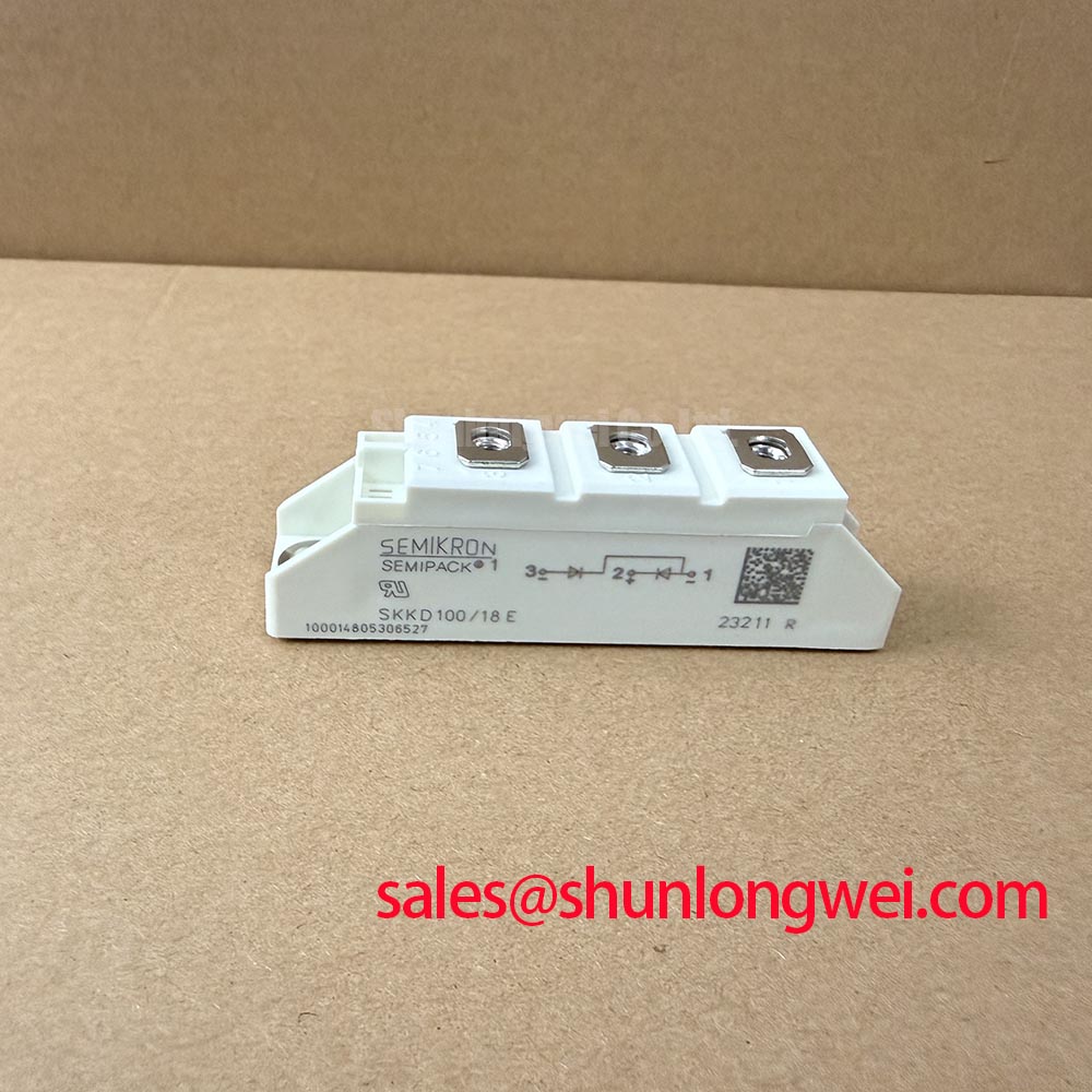
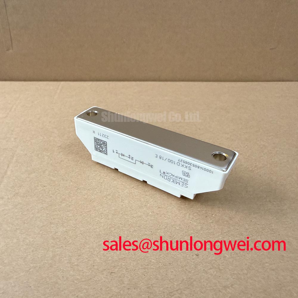
- Confirm the complete module marking, polarity, terminal identification, and voltage rating against the replacement record and the exact variant’s datasheet.
- Inspect the baseplate, heatsink contact area, thermal interface, and terminal hardware for distortion or contamination.
- Verify the driver and protection circuit topology before applying any trigger signal, because SKKD modules are diode modules, not gate-controlled thyristors.
Semikron SKKD is a rectifier diode module family evaluated here for rectifier positions in industrial power equipment, including suitably rated circuits within three-phase motor solid-state soft starters. The ratings listed below describe a 400 V VRRM, 500 V VRSM configuration with an average forward current rating of 47 A IFAV under the stated sinusoidal 180° and case-temperature conditions. SKKD alone is not a complete part number: confirm the full type designation and its datasheet before applying these values. A 400 V reverse-voltage rating does not establish suitability for a 400 V AC supply.
| Parameter | Listed Specification—Verify Against Exact Variant | Engineering Significance |
|---|---|---|
| VRRM | 400 V at Tvj 25°C to 125°C | Maximum repetitive peak reverse voltage |
| VRSM | 500 V at Tvj 25°C | Non-repetitive peak reverse-voltage rating |
| IFAV | 47 A, sinusoidal 180°, Tcase 85°C | Average forward-current rating under the stated conditions |
| IFRMS | 90 A | RMS forward-current limit; thermal limits also apply |
| IFSM | 700 A, 10 ms pulse at Tvj 25°C | Peak forward surge-current capability |
| I2t | 2450 A²s, 10 ms pulse at Tvj 25°C | Fuse coordination and fault-current integral reference |
| VF | 1.95 V maximum at Tvj 25°C and IF 250 A | Forward-voltage reference at the stated test point |
| Rth(j-c) | 0.6 K/W per diode; 0.3 K/W per module | Junction-to-case thermal design input |
| Visol | 3000 V AC rms for 1 minute; 3600 V AC rms for 1 second | Terminal-to-baseplate isolation test rating |
Assembly Integrity and Layout Architecture for I2t Fuse Coordination
Fuse coordination should begin with the exact module’s verified I2t rating, not with the nominal motor current alone. If the listed 2450 A²s value applies, its stated pulse duration and initial junction temperature must be included in the review. The selected semiconductor fuse and its manufacturer’s time-current data must be checked against the complete prospective fault waveform, including the fuse clearing integral and the module’s stated surge capability. A suitable coordination review compares the fuse total clearing I2t with the diode and thyristor withstand data in the actual soft-starter topology.
In a three-phase soft starter, keep the high-current path short and mechanically stable from the line connection through the module and into the bypass or motor circuit. Busbar symmetry is a Design Consideration because unequal conductor geometry can increase current sharing imbalance and switching overshoot. The system engineer should verify the resulting peak voltage during controlled switching and, where required, properly contained fault testing by qualified personnel rather than infer it from the 400 V reverse-voltage rating.
Use the manufacturer’s specified terminal hardware and assembly procedure for tightening force, conductor preparation, and baseplate mounting. Excessive mechanical force can distort the package or reduce heatsink contact, while loose power terminals can create localized heating. Safety Interlock Note: isolate and discharge the soft-starter power circuit before removing terminals or changing the module.
For comparison work, engineers assessing a higher-current rectifier family can review SKKD380 as a separate reference; its ratings must not be transferred to another SKKD variant without a circuit-level compatibility review.
Preventing Spurious Faults: Trigger-Current Dynamics and Device Topology
The SKKD ratings listed here identify forward and reverse diode ratings, surge current, thermal resistance, and isolation voltage; they do not establish a gate-trigger current, gate-pulse rise-time, or holding-current specification. Do not apply a presumed gate-drive profile to the module terminals. First identify whether the installed assembly uses SKKD as a rectifier module beside separately controlled thyristors.
Where a controlled thyristor stage is present, the gate circuit should be assessed as a system function. Designers should verify pulse amplitude, pulse duration, trigger-current rise behavior, gate-pulse tail current, and synchronization across all phases using the actual device documentation. Thyristor latching and holding-current requirements apply to anode current, not gate current. Multi-pulse firing can be considered where the control architecture requires reliable latching under changing load conditions, but the pulse strategy remains system-dependent.
Localized heating or intermittent conduction should be investigated through phase-to-phase comparison, driver isolation checks, and oscilloscope measurements at the external thyristor’s gate-to-cathode reference using appropriately rated isolated or differential probes. A distorted pulse may result from wiring inductance, isolation-device limitations, ground-reference movement, or a damaged external thyristor; the waveform should be compared with a known-good channel before assigning the fault to SKKD. The Semikron SEMIPACK® Thyristor / Diode Module documentation provides useful product-family context, while the Semikron CAL Diode Technology page offers broader diode technology reference, not confirmation of the technology used in a particular SKKD variant.
Benchtop Waveform Tuning Through Baseplate Thermal Resistance
Thermal validation should use the exact variant’s verified junction-to-case thermal resistance. If the listed Rth(j-c) values of 0.6 K/W per diode and 0.3 K/W per module apply, use them according to the datasheet’s loading assumptions; the module value must not be substituted for the per-diode value when calculating an individual junction temperature. These values do not replace measurement of heatsink flatness, interface coverage, airflow, or enclosure temperature. Apply a uniform thermal interface layer using the equipment builder’s controlled process, then tighten the baseplate evenly according to the applicable mechanical instructions.
During a benchtop run, monitor each phase under comparable current and switching conditions. A temperature imbalance between otherwise similar paths can point to unequal busbar resistance, non-uniform mounting pressure, poor interface spreading, or unequal electrical loading. Recheck the terminal seating and heatsink contact before changing the electrical waveform.
For a motor cable with significant length, sufficiently fast switching edges can interact with cable impedance and produce reflected-voltage stress at the motor or semiconductor terminals. This is especially relevant to fast-switching inverter stages and should not be assumed to dominate a line-frequency soft starter. Designers should evaluate the complete cable, snubber, filter, and busbar arrangement with differential and common-mode measurements. The objective is to minimize parasitic loop inductance and control switching overshoot while verifying the measured peak remains within the applicable reverse-voltage and insulation boundaries.
In bidirectional DC to DC battery systems, repeated charge and discharge operation can create thermal cycling across the power path. SKKD may be evaluated only where its rectifier topology and current direction match the converter architecture; the diode module itself does not provide controlled bidirectional power flow. Junction temperature, case temperature, cooling transitions, and electrical cycling should be correlated during validation. The Field Engineer’s Handbook provides supporting guidance for structured testing and failure analysis.