

Content last revised on September 24, 2026
Transient Dynamics & Electrical Design: Non-Repetitive Surge On-State Current on SKKE1201/22
| Manufacturer | Semikron |
|---|---|
| Part Number | SKKE1201/22 |
| Category | Thyristor/Diode Module |
| Package | Isolated Module |
| Topology | General Power Stage |
| Series | Standard |
With the cabinet isolated from the supply, inspect the SKKE1201/22 main terminals for heat discoloration, loosened hardware, carbon tracking, and evidence of a distorted mounting face before reconnecting any test leads. A cold resistance check across external power paths can identify an obvious short condition, but it cannot establish switching health, surge capability, or junction condition in a thyristor and diode assembly.
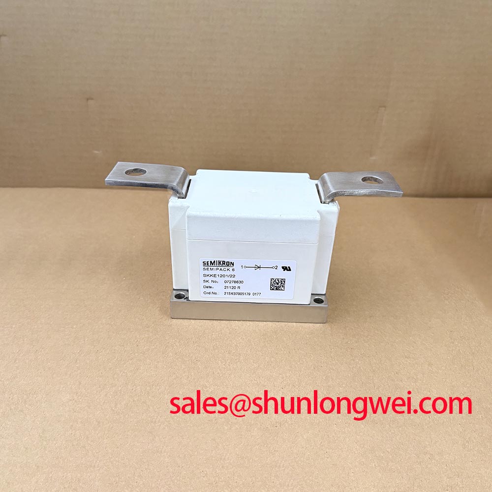
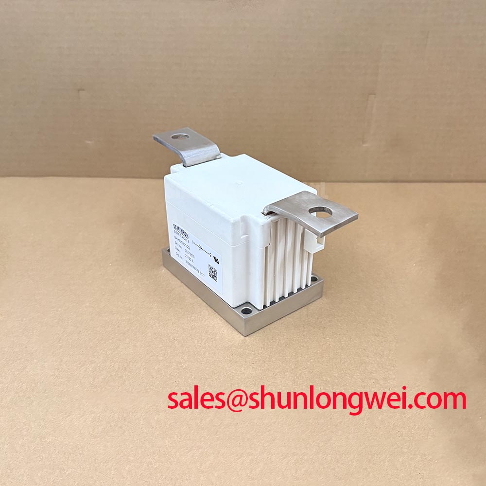
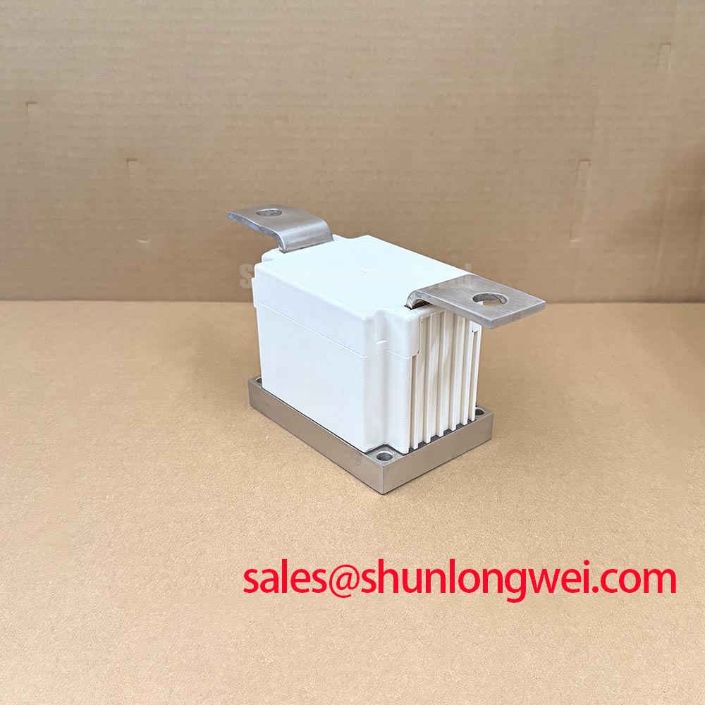
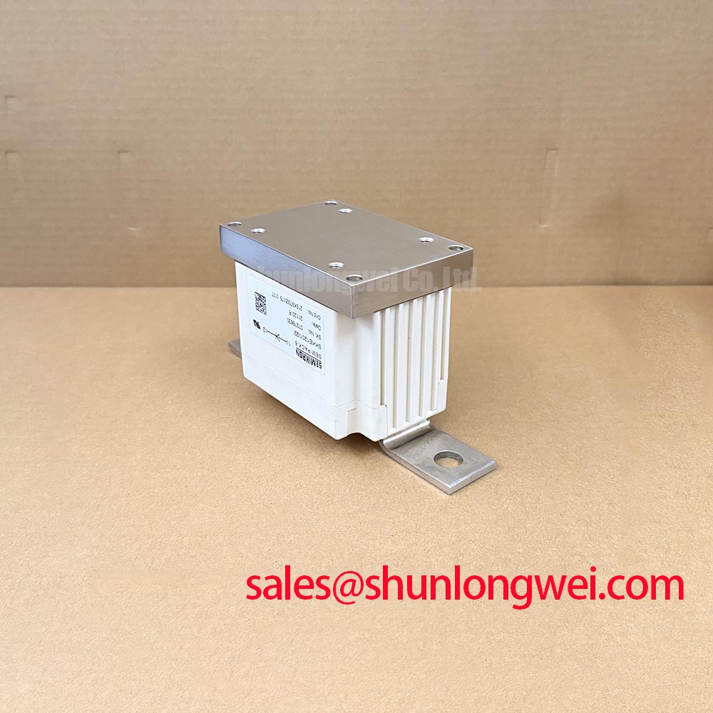
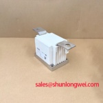
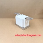
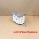
The SKKE1201/22 is specified as a Semikron Thyristor/Diode Module in an isolated module package. For a surge event that follows a line disturbance or capacitor-bank fault, the relevant manufacturer information includes the part-specific non-repetitive surge-current rating, associated conditions, and fuse coordination information in the applicable documentation. These values must be matched to the installed unit rather than inferred from the part-number format.
During a documented 10 ms half-cycle event, verify the recorded current waveform, pre-fault load state, protective-device operation, and the interval before reverse voltage is reapplied. This provides the evidence needed to judge whether the event remained inside the original electrical boundary. A waveform that is clipped, asymmetric, or accompanied by a delayed fuse operation requires inspection of the surrounding commutation path as well as the module.
For power-stage context, Semikron describes its SEMIPACK thyristor and diode module family as a power-semiconductor module platform. The installed SKKE1201/22 should still be assessed against its own approved rating documentation and the equipment schematic.
Field Alert: De-energize, discharge the DC and capacitor-bank energy paths, and verify absence of voltage before loosening a power terminal or removing the isolated module from its heatsink.
SKKE1201/22 Circuit Protection & Reliability: Calibrating Surge Energy Dissipation and Clamping Voltage
Probe the voltage directly across the power-stage connection during a controlled switching observation, using a measurement method rated for the circuit, and compare the captured transient with the equipment’s approved limits. A high peak can arise from external line disturbance, cable inductance, capacitor-bank switching, degraded clamping components, or an RC network whose condition has changed.
MOV and RC snubber networks belong to the system protection design, not to the published core identity of this isolated thyristor/diode module. As a Design Consideration, inspect the MOV for mechanical damage or thermal distress and check the RC network, its wiring route, and terminal integrity. The system engineer should determine the clamping level and energy capability from the actual supply, fault environment, and measured transient waveform.
IEC 61000-4-5 is commonly referenced when equipment immunity to surge phenomena is evaluated, but it is an equipment-level test framework. It does not establish an individual module rating or prove that a semiconductor assembly independently meets system EMC requirements. In a grid-tied static var compensator or thyristor-switched capacitor installation, confirm the protection response against the complete cabinet arrangement, including buswork, fuses, capacitors, and control timing.
When a repair investigation finds a damaged suppression network, retain the original component values and connection topology from the equipment documentation. Changing those elements without validating the resulting peak voltage, thermal loading, and commutation behavior can shift stress to the replacement module or adjacent components.
Assembly Integrity & Layout Architecture: Implementing Type-2 Coordination: Sub-Cycle Dead-Short for SKKE1201/22
Trace each conductor from the SKKE1201/22 terminal to its semiconductor fuse and busbar, then check for looseness, fretting debris, damaged lugs, and unequal contact pressure. A local high-resistance connection can create heat and waveform distortion that resembles an internal semiconductor fault, particularly after repetitive capacitor-bank operations.
Type-2 coordination is a system-level protection objective. Its suitability depends on the selected semiconductor fuse, prospective fault current, clearing behavior, contactor or switching arrangement, conductor geometry, and the withstand capability documented for the installed device. The fuse’s pre-arcing and total clearing I2t information must be evaluated against the relevant module data under the actual prospective dead-short condition; neither value should be treated as interchangeable with a generic fuse label.
The isolated package supports a defined mechanical installation interface, but its electrical protection outcome is determined by the full assembly. Use clean, flat mating surfaces, appropriate thermal-interface material, and the equipment manufacturer’s fastening procedure. Verify that busbars align without applying side load to module terminals and that return paths remain compact where they influence fault and commutation loops.
For practical inspection sequences, controlled measurements, and fault evidence recording, use the Field Engineer’s Handbook as a reference alongside the equipment schematic and approved maintenance procedure.
Benchtop Waveform Tuning: Mitigating Stress by Minimizing Commutation Turn-Off Voltage Spikes on SKKE1201/22
Capture the commutation voltage and current at the module connection points while the repaired power stage operates at a controlled condition, then compare both traces with a known-good channel or validated commissioning record. Ringing, unusually sharp recovery behavior, or inconsistent phase-to-phase traces may indicate a layout, snubber, connection, trigger-timing, or associated diode-path issue and should be investigated as a system interaction.
Reverse-recovery peak current and recovery time are device-specific characteristics that depend on defined test conditions. They are not included in the supplied official specification set for SKKE1201/22, so no numeric recovery claim should be assigned to this unit without the applicable manufacturer data. The appropriate engineering task is to observe the installed waveform and verify its peak margins against the equipment’s permitted electrical limits during switching tests.
As a Design Consideration, minimize parasitic loop inductance where the commutation path produces turn-off overshoot, while preserving the original circuit architecture. Confirm probe placement and bandwidth before attributing a narrow spike to the module, since measurement-loop pickup can misrepresent a fast transient. Inspect paired power paths and parallel conductors for equivalent connection quality because static continuity alone does not verify dynamic current sharing.
For material handling during repair planning, SKKH106-14E can be reviewed as a separate thyristor module reference. Any substitution decision requires verification of circuit function, terminal arrangement, insulation requirements, electrical ratings, thermal interface, protection coordination, and control compatibility by the responsible system engineer.