

Content last revised on October 27, 2026
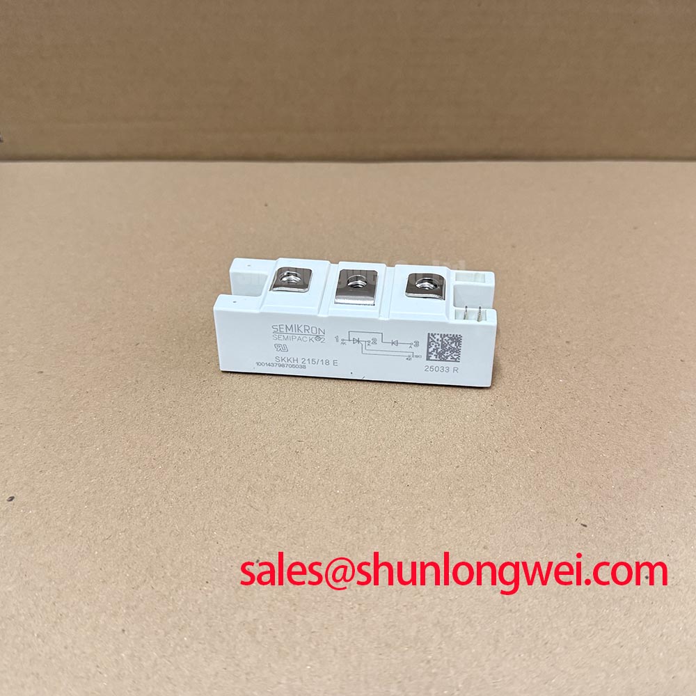
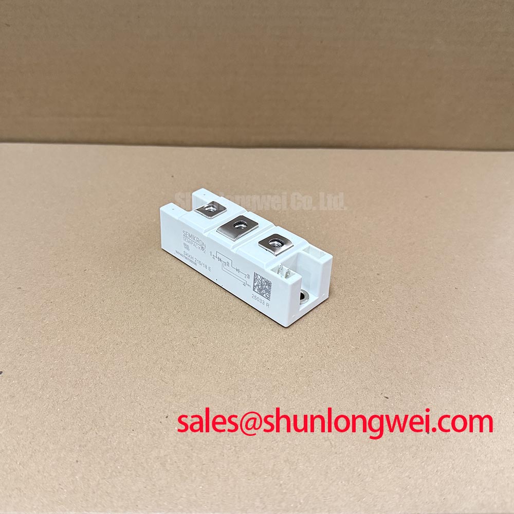
SKKH215/18E Incoming Inspection and Product Identification
- Isolate the rectifier, discharge stored energy, and match the module’s terminal markings to the equipment schematic before taking cold-state measurements.
- Disconnect parallel circuit paths before comparing diode-mode readings; record probe polarity, instrument range, and module temperature.
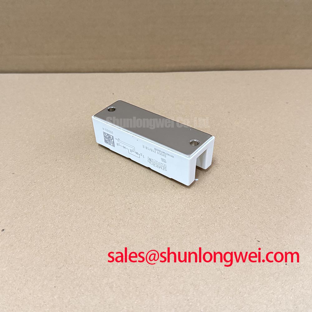
- Inspect the mounting surface, terminal contact faces, and gate connections for conditions that could disturb thermal contact or triggering.
- Separate main-circuit blocking-voltage checks from terminal-to-baseplate insulation testing; each requires its own approved procedure.
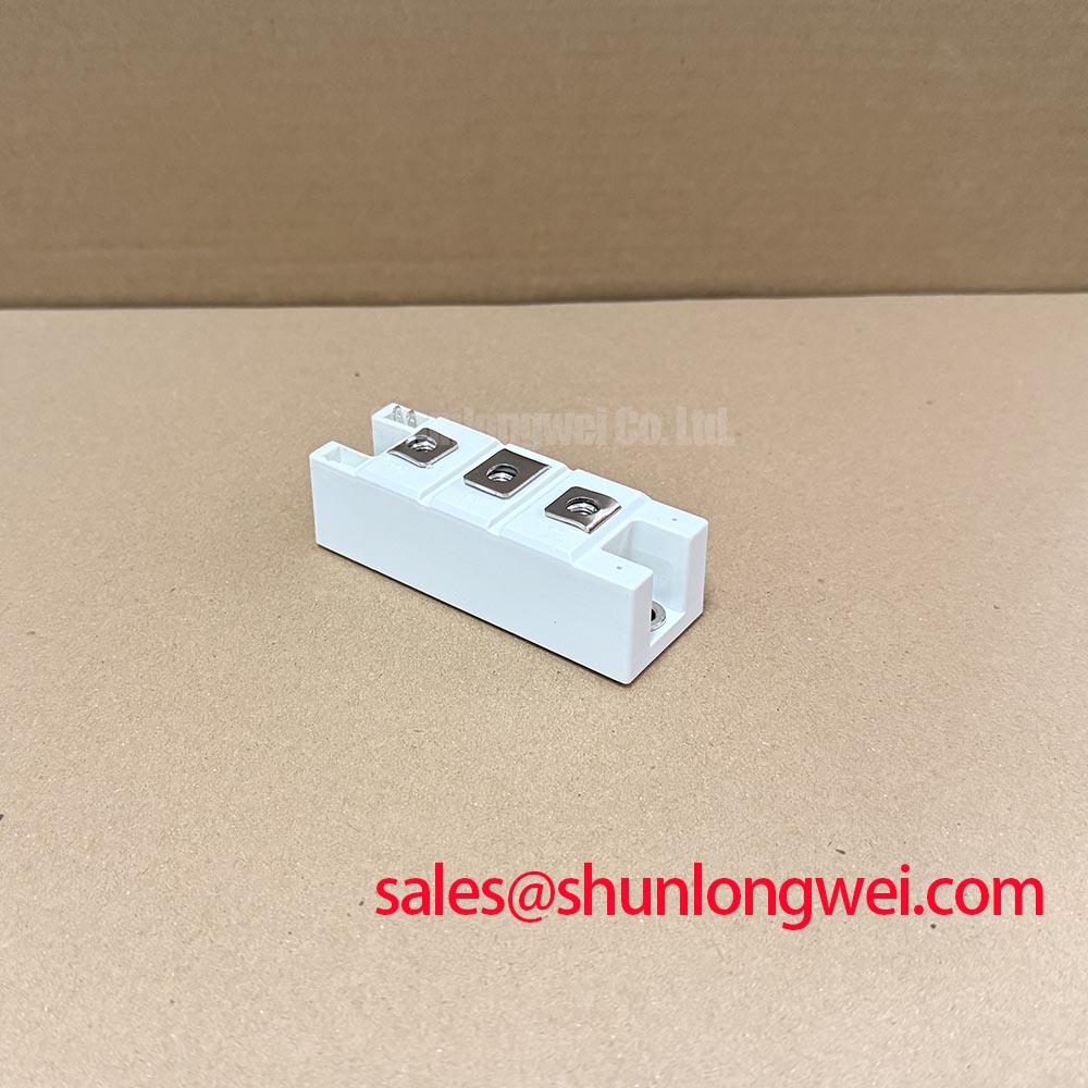
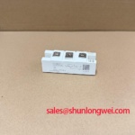
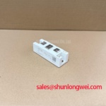
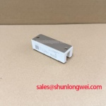
The SKKH215/18E is a Semikron thyristor/diode module with an 1800 V blocking-voltage rating in the 215 A current class, housed in a SEMIPACK package. The applicable current-rating conditions must be checked in the datasheet. Incoming inspection should establish terminal identity and repeatable static behavior before powered evaluation.
| Product characteristic | Specification or Reference |
|---|---|
| Model | SKKH215/18E |
| Manufacturer | Semikron |
| Blocking-voltage rating | 1800 V |
| Current class | 215 A; consult the datasheet for rating conditions. |
| Package family | SEMIPACK |
| Condition-dependent evaluation data | Consult Datasheet for current-rating conditions, terminal diagram, recovery characteristics, surge ratings, gate limits, insulation test conditions, and mounting torques. |
Bench Tip: With the module isolated and discharged, use appropriate ESD precautions and compare cold-state readings with a known-good module under the same instrument settings.
SKKH215/18E Thermal-Electrical Optimization: Minimizing Commutation Voltage Spikes
Measure the diode commutation waveform at the module terminals rather than relying on a remote bus measurement. As a Design Consideration, probe placement and measurement-loop area affect the apparent reverse-recovery peak current and voltage ringing. Evaluate reverse-recovery peak current, I_rrm, and recovery time, t_rr, alongside forward current, junction temperature, and commutation rate; these conditions are essential to interpreting recovery behavior.
A multimeter diode test provides a low-energy comparison, not a recovery measurement. Record the forward indication in the documented conducting direction and compare the reverse indication after disconnecting external paths. An unexpected reading warrants checking terminal identity and circuit isolation before attributing it to the semiconductor. The thyristor branch also requires appropriate triggering conditions; its untriggered reading should not be interpreted as an ordinary diode result.
For package-family context, Semikron’s SEMIPACK thyristor/diode module information provides the relevant product framework. The manufacturer’s CAL diode technology information concerns diode technology, but does not establish that this specific module uses CAL dies or shares their recovery characteristics.
Engineering Recommendation: minimize commutation-loop area and maintain sound terminal contact to reduce inductive overshoot. Apply the module-specific mounting and terminal torques separately, checking heatsink flatness and interface condition. Validate the resulting voltage peaks and thermal behavior in the actual assembly rather than assigning a universal busbar or snubber value.
SKKH215/18E Surge Protection: Sinusoidal 10 ms Half-Cycle Guidelines
Match a surge event to the specified waveform and initial junction temperature before comparing it with the thyristor’s non-repetitive surge-current rating, I_TSM. A sinusoidal 10 ms half-cycle rating describes a defined transient test; it is not permission for repetitive overload operation. Reverse-voltage reapplication conditions also matter when assessing whether the device can recover blocking capability after the surge.
Engineering Recommendation: build the fuse coordination record around the module’s applicable I²t limit and the fuse manufacturer’s total-clearing I²t at the relevant circuit conditions. Include prospective fault current, operating voltage, initial temperature, and clearing behavior. Comparing nominal fuse current with the module’s 215 A designation alone does not establish semiconductor protection.
During incoming inspection, check blocking behavior and insulation through separate test arrangements. Main-terminal blocking voltage concerns semiconductor junctions; terminal-to-baseplate insulation concerns a different electrical path. Select test voltage, duration, connections, and acceptance criteria from the applicable manufacturer procedure, without treating the 1800 V rating as an insulation-test setting.
For replacement assessment, the SKKD380 comparison offers rectifier-module context, not evidence of interchangeability. A diode module cannot replace a controlled thyristor branch solely because voltage ratings appear comparable; circuit function, terminal mapping, mounting geometry, and protection coordination remain decisive.
SKKH215/18E Circuit Protection & Reliability: Turn-On Current-Rise Limiting
Check gate-current delivery at the thyristor’s gate-to-cathode connection while observing anode-current rise. As a Design Consideration, inadequate triggering and excessive current rise can impair current spreading during turn-on. Evaluate trigger current, trigger voltage, pulse duration, and any pulse-train strategy against the device limits and the equipment’s firing circuit.
Engineering Recommendation: assess RC snubbers against measured reapplied voltage and commutation behavior, and evaluate a series reactor only where the circuit requires current-rise limitation. Component selection belongs to the complete power-stage design. The IGBT Design & Integration resource provides broader thermal and layout context, but IGBT gate-drive practices should not be transferred directly to thyristor triggering.
For a high-current green hydrogen electrolyzer DC rectifier, integration assessment should cover controlled-bridge topology, firing synchronization, cooling, and fault isolation. Do not assume this module functions as a self-turn-off regenerative braking chopper, or that parallel branches share current through an established positive temperature coefficient. Where parallel operation is proposed, verify static sharing, trigger timing, connection symmetry, and thermal balance under representative load conditions.