Content last revised on October 5, 2026
SKKH91-12E Circuit Protection and Reliability: Checking the Thermal Interface
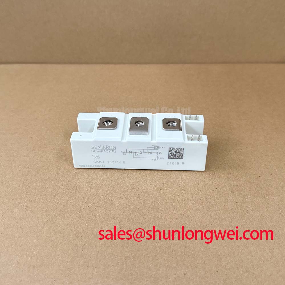
With the power isolated and stored energy discharged, compare the terminal layout and cold-state resistance of the installed module with the replacement documentation before loosening the heatsink. SKKH91-12E is identified as a Semikron SEMIPACK thyristor/diode module. The supplied product record lists 200.0 V and 911.0 A, but those figures should not be treated as verified manufacturer ratings: obtain the exact Semikron datasheet and confirm the voltage, current, terminal diagram and suffix before approving a replacement.
Before removing the installed module, photograph its terminal connections and record the orientation of its baseplate on the heatsink. After removal, inspect the contact pattern left by the thermal interface material. A patchy imprint, debris or a visibly uneven seating surface can indicate poor contact, but the imprint alone does not establish the cause of an overtemperature fault. Check the heatsink surface and mounting hardware, then compare the measured operating conditions with the manufacturer’s junction-to-case thermal-resistance specification once the correct datasheet has been identified.
Apply thermal interface material uniformly and tighten the mounting hardware in accordance with the applicable module documentation. Do not transfer a torque value from another SEMIPACK package simply because its outline appears similar. Field alert: Do not energize a high-voltage soft starter using the supplied 200.0 V listing figure as proof of the SKKH91-12E blocking-voltage rating.
For short-circuit protection, compare the proposed fuse’s clearing behavior with the module’s published surge-current and I²t limits under the relevant operating conditions. Without those confirmed limits, neither a fuse size nor a protection margin can be specified for this unit. Semikron Danfoss’s SEMIPACK thyristor and diode module information provides product-family context; the exact part datasheet remains the authority for ratings and mounting instructions.
Benchtop Waveform Tuning: Assessing Surge Protection and Clamping
On a repair bench, trace the incoming supply, protective devices and module terminals against the equipment schematic before changing a varistor or snubber. A three-phase motor soft starter is a possible application to evaluate, not evidence that this module fits a particular machine. Its line voltage, transient environment, firing arrangement and existing protection must all be checked against the confirmed SKKH91-12E specifications.
A metal-oxide varistor can help limit incoming transients, while an RC network can shape voltage across a switching device. Neither can be selected from the module name alone. As a Design Consideration, measure the surge and switching waveforms at the relevant terminals, account for the protective devices already present, and have the system engineer verify the resulting peak voltage against the module’s confirmed blocking rating. Do not assume that a reference to a surge-test standard establishes compliance for a module or for the completed soft starter.
If a front-end rectifier appears on the schematic, SKKD162/12 is a separate module to assess by its own ratings and connections; its presence does not determine the SKKH91-12E gate-drive requirements. Likewise, Semikron Danfoss’s bare-die technology information describes technology context, not the verified surge capability of this assembled part.
Preventing Spurious Faults: Verifying Gate Triggering Across Temperature
With the original control arrangement documented, inspect the gate leads for loose connections and compare firing waveforms across the affected and unaffected phases. A missing pulse, noise pickup or an inconsistent pulse train may suggest a control-path problem; it does not, by itself, prove a failed thyristor. Confirm gate and cathode terminal identification from the exact module diagram before attaching an oscilloscope or test driver.
Gate trigger current, pulse duration and temperature dependence require the part-specific datasheet. No minimum gate-current slew rate, back-porch current or multi-pulse scheme should be imposed on SKKH91-12E without that documentation and the equipment designer’s firing specifications. As a Design Consideration, check that the gate signal remains adequate throughout the intended operating temperature range, then verify actual turn-on behavior under controlled conditions. Keep the test within the manufacturer’s confirmed gate limits.
When evaluating another part, such as SKKT273/12E, compare its circuit configuration, gate requirements, terminal positions, thermal interface and verified electrical ratings with the installed unit. A similar package or model suffix is not sufficient evidence of interchangeability.
Field Diagnostics and Commissioning: Checking the RC Snubber Network
Before recommissioning, inspect the installed snubber resistor and capacitor, their wiring and the connections to the module. Measure components with the circuit safely isolated and compare the results with the equipment schematic. If a series reactor is fitted, record its position and condition rather than assuming it is required in every SKKH91-12E circuit.
As a Design Consideration, minimize stray wiring effects where they contribute to unwanted turn-on or switching stress, then assess the terminal-voltage and current waveforms during controlled tests. Snubber resistance, capacitance and any reactor selection are system-level decisions: the equipment engineer should establish them from the actual circuit and verify that measured peaks remain within the module’s confirmed limits. The IGBT Design & Integration guide offers broader context on switching loops and thermal interfaces, but its IGBT gate-drive guidance must not be applied as a thyristor specification.
If the repaired phase behaves differently from the others, compare its gate signal, voltage waveform, protection components and mechanical connections before assigning a cause. Record the measured conditions and the exact datasheet revision used for the final compatibility check.