Content last revised on October 10, 2026
SKKT72-12E Circuit Protection & Reliability: Calibrating Harmonic Current Injection and Line Filter
- Isolate the SVC cabinet, discharge stored energy, and verify absence of voltage before recording the existing terminal arrangement and disconnecting the module.
- Check cold-state terminal impedance against a known-good phase path using an appropriately rated instrument.
- Inspect heatsink flatness, thermal interface condition, terminal hardware, and signs of localized heating.
- Verify the firing circuit insulation and line-filter condition before applying operating voltage.
SKKT72-12E is a Semikron SEMIPACK dual-thyristor module in the 1200 V, 72 A class. The current designation is not an unconditional continuous operating limit; allowable current depends on the datasheet conditions and thermal design. In a grid-tied Static Var Compensator or thyristor-switched capacitor installation, the module should be evaluated together with the firing circuit, semiconductor fuse coordination, line reactor, snubber network, and thermal assembly.
| Manufacturer | Semikron |
| Part number | SKKT72-12E |
| Product category | Dual-thyristor module |
| Package | SEMIPACK |
| Repetitive blocking voltage | 1200 V |
| Nominal current class | 72 A; refer to the exact datasheet for rating conditions |
When investigating harmonic current in an SVC branch, first separate firing-angle behavior from a defective power path. For a phase-controlled reactor branch, the controller should be checked across its permitted firing range while the technician records line current and reactive-power response. For a thyristor-switched capacitor branch, verify the commanded switching sequence and synchronization rather than sweeping the firing angle. A smooth change in the measured waveform supports a control-path investigation; abrupt phase imbalance requires attention to terminal connections, fuse condition, commutation behavior, and the associated line filter.
The 1200 V blocking-voltage rating and 72 A current class must be evaluated against the actual branch voltage, current waveform, fault level, switching duty, and datasheet rating conditions. They do not replace coordination with the semiconductor fuse. The selected fuse must be checked against the manufacturer’s I²t coordination data and the prospective fault current of the installation. If that coordination table is not available for the exact assembly, do not infer a fuse value from the module current label alone.
Terminal surfaces should be clean, flat, and free from oxide or loosened hardware. Use the original terminal arrangement and the applicable Semikron mechanical instructions for tightening torque rather than applying a generic value. The heatsink interface also deserves attention: old or displaced thermal compound can create a local temperature rise even when the electrical waveform appears acceptable. The Semikron SEMIPACK® Thyristor / Diode Modules reference provides useful product-family context for mechanical and electrical evaluation.
SKKT72-12E Operational Boundaries: Evaluating RC Snubber Network Optimization to Prevent Limits
An RC snubber should be assessed as part of the complete commutation loop, not as an isolated accessory. Record the capacitor-bank switching sequence, line impedance, reactor condition, and voltage waveform at the module terminals. A poorly matched snubber can leave excessive transient stress across the thyristor, while an unsuitable capacitor or resistor can increase discharge current and introduce additional losses.
For spurious turn-on investigations, inspect the physical loop between the module, snubber, line filter, and capacitor bank. Keep the high-current switching path compact and verify that the snubber connection is made at the intended electrical points. The system designer should select Rs and Cs from measured transient behavior, device limits, pulse repetition, and thermal conditions. These are Engineering Recommendations for system validation, not factory parameters of the SKKT72-12E.
Series saturable reactors may be considered where the installation experiences a severe current rise during capacitor energization. Their suitability depends on the actual branch topology and control sequence. Validate the result by observing phase-current balance, checking fuse operation history, and reviewing terminal temperature after representative switching duty. MOV coordination should also be reviewed as a Design Consideration for incoming overvoltage absorption; the MOV rating, energy capability, and protective location must be selected for the complete system rather than inferred from the module label.
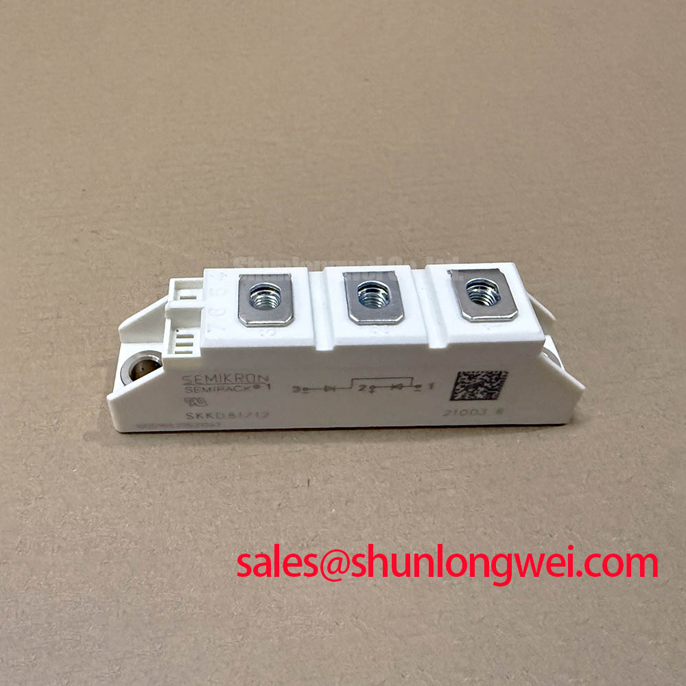
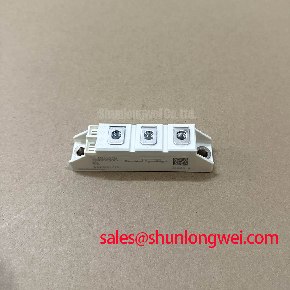
For comparison during service planning, engineers may review the SKKD 81/12 as a separate Semikron diode module. It is not a direct replacement for the SKKT72-12E dual-thyristor module; its uncontrolled diode circuit cannot perform the same firing-controlled function.
Preventing Spurious Faults: Surge-Current and Thermal Margins for SKKT72-12E
Peak-current verification should begin with the actual waveform recorded during energization, fault clearing, or capacitor-bank switching. Compare the observed surge waveform and duration with the applicable manufacturer data for ITSM, I²t, junction temperature, and recovery conditions. The 72 A current class does not establish surge capability or repetitive thermal performance; those limits must be taken from the relevant technical documentation for the exact device configuration.
Before forward blocking voltage is reapplied, confirm that the thyristor has had sufficient recovery time under the applicable commutation conditions and that the line filter, reactor, and snubber have not introduced abnormal ringing. High peak current can produce localized heating when current is unevenly shared or when a connection has excessive contact resistance. Review phase balance, fuse coordination, heatsink contact, and thermal compound coverage as one maintenance task.
Thermal cycling is especially relevant in SVC branches and capacitor-switched power assemblies. Designers should monitor temperature rise at the module mounting interface and evaluate the effects of repeated switching transitions on the complete assembly. Periodic heatsink cleaning, inspection of thermal interface material, and verification of airflow help preserve the intended thermal path.
Maintenance Note: De-energize, discharge stored energy, and verify absence of voltage before touching terminals or cleaning the cabinet. Check operating contact temperatures only with an appropriate non-contact method and the required electrical safety procedures.
For broader system-level discussion of converter topology and switching efficiency, consult the Peak Efficiency in Solar and Energy Storage engineering guide. The Semikron bare-die product resource can also provide general semiconductor technology context, distinct from the specific published limits of this module.