




Content last revised on October 23, 2026
SKM300GA12T4 Thermal-Electrical Optimization: Suppression of Reflected-Wave Voltage Overshoot at Practical Tuning
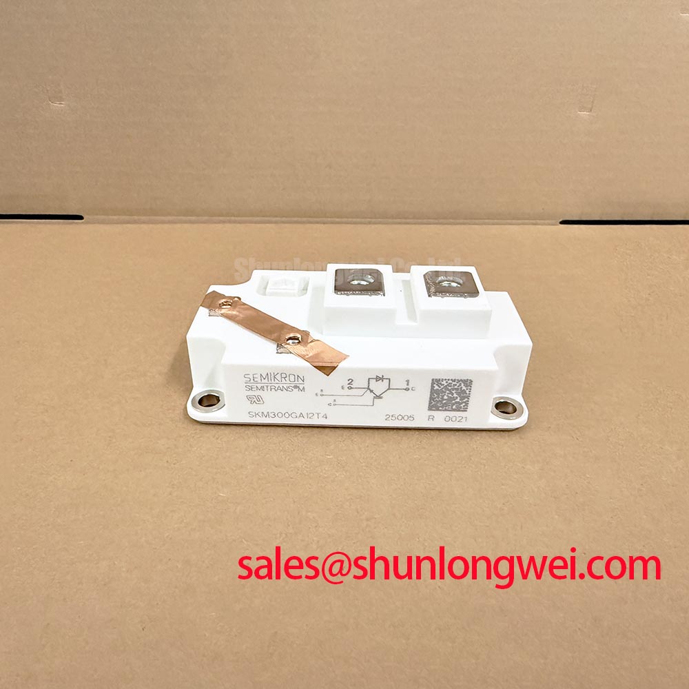
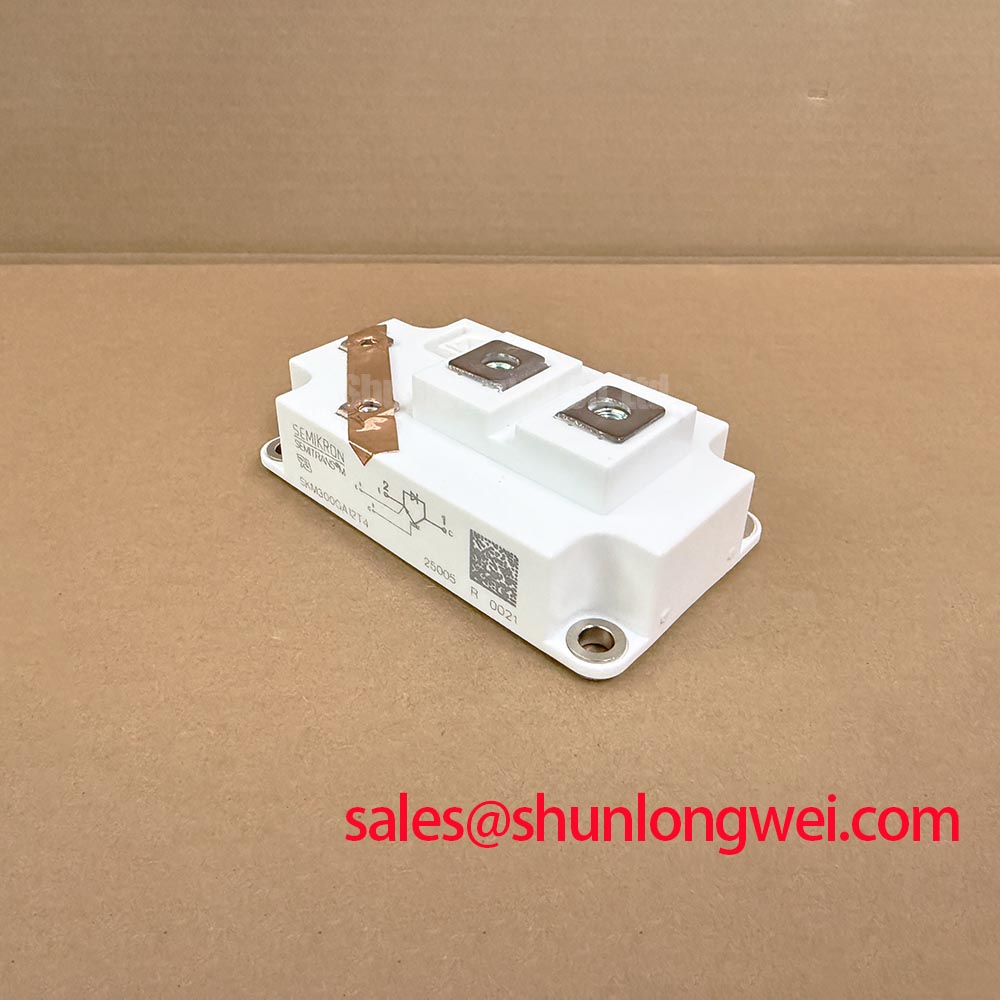
With the DC link isolated and verified discharged, check the module marking and terminal connections against the equipment schematic before reconnecting the gate driver. The SKM300GA12T4 is a Semikron IGBT module with official ratings of 1200 V and 300 A in a Semitrans package. Those ratings establish its electrical class; commissioning still requires matching the cooling arrangement, switching conditions, and protection response to the actual assembly.
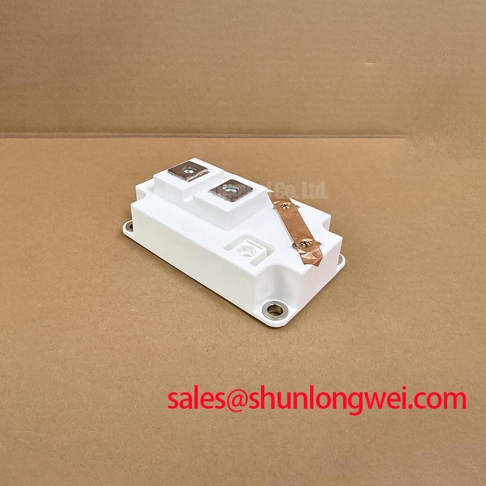
For procurement and repair assessment, retain the complete part designation alongside the mechanical drawing and circuit diagram. A heavy-duty variable-frequency AC motor drive is one potential integration context, subject to electrical, mechanical, and protection compatibility.
SKM300GA12T4 Thermal-Electrical Optimization: Suppression of Reflected-Wave Voltage Overshoot at Practical Tuning
Compare the inverter output waveform with the voltage measured at the motor terminals when investigating cable-related overshoot. Design Consideration: impedance mismatch between a motor cable and its termination can produce reflected waves, with terminal voltage approaching twice the incident voltage step under particular conditions. This is a transmission-line effect, not an SKM300GA12T4 operating specification, and it must be distinguished from collector-emitter overshoot inside the converter.
Use appropriately rated differential measurement equipment and a probe arrangement that minimizes measurement-loop pickup. Record cable configuration, DC-link voltage, switching conditions, and load state alongside the waveforms. A comparison made under different operating conditions can obscure whether a change comes from the cable termination, switching transition, or measurement arrangement.
When evaluating an output choke or dv/dt filter, designers should consider cable characteristics, motor insulation requirements, filter losses, resonance, and the drive control strategy. Filter selection should follow the filter supplier’s application limits and system measurements rather than the module’s current rating alone. Maintain terminal spacing and conductor routing according to the equipment’s insulation-coordination requirements; no universal clearance follows from the package name.
Engineering Recommendation: keep motor-terminal reflection analysis separate from semiconductor switching-loss assessment. Fourier series decomposition for inverter output waveform harmonic analysis provides background for periodic waveform analysis, whereas fast reflected-wave peaks require time-domain measurements.
Preventing Spurious Faults: Static and Dynamic Current Distribution Guidelines for SKM300GA12T4
Compare gate-emitter waveforms and branch currents under matched operating conditions before attributing unequal loading to the modules themselves. Design Consideration: a positive temperature coefficient of on-state voltage can support static current sharing within the applicable current and temperature region. Apply that principle only after checking the device characteristic curves; it does not establish automatic balance throughout the operating range.
Dynamic sharing depends on gate-drive timing, gate-loop impedance, power-path inductance, and thermal conditions. For parallel arrangements, designers should evaluate symmetrical current paths and comparable cooling. Where a documented auxiliary emitter connection is provided, route the driver return according to the terminal diagram rather than sharing a high-current return path. This helps control common-emitter coupling without assuming an undocumented terminal arrangement.
The CM300HA-24E can enter a cross-model assessment, but its inclusion is not a drop-in replacement recommendation. The comparison below separates established SKM300GA12T4 specifications from the evidence needed for substitution.
| Selection item | SKM300GA12T4 | CM300HA-24E assessment |
|---|---|---|
| Manufacturer | Semikron | Consult manufacturer datasheet |
| Rated voltage | 1200 V — Official Specification | Compare blocking rating and switching conditions |
| Rated current | 300 A — Official Specification | Compare rating conditions and thermal limits |
| Package | Semitrans — Official Specification | Compare outline, mounting, and terminal positions |
| Replacement-critical characteristics | Consult datasheet for circuit, gate, and thermal characteristics | Match topology, driver compatibility, and protection behavior |
For a high-side driver using bootstrap power, capacitor selection should account for gate charge at the selected drive conditions, driver quiescent consumption, leakage, permissible supply droop, and the longest interval without recharge. Verify recharge opportunity across the commanded duty-cycle range. Inspect supply voltage at the driver during switching because an apparently adequate unloaded supply does not establish high-side power integrity.
SKM300GA12T4 Thermal-Electrical Optimization: Type-2 Coordination: Protecting IGBT Module at Practical Tuning
Review semiconductor fault turn-off and upstream fuse interruption as separate protection functions. Design Consideration: a fuse’s total clearing I²t cannot, by itself, establish that an IGBT survives a DC-link short circuit. IGBT short-circuit withstand is conditional on gate voltage, DC-link voltage, junction temperature, and fault duration; coordination requires the relevant manufacturer limits and the complete fault-current path.
Check the driver’s fault detection, blanking behavior, controlled turn-off, and fault-latch operation against the equipment protection scheme. Then assess fuse interruption capability, circuit voltage, prospective fault current, and stored DC-link energy. Prevention of enclosure or module damage requires validated assembly-level protection; it is not a result that can be guaranteed from nominal module and fuse ratings.
The term Type-2 coordination should not be treated as an independent certification of this IGBT module. Where an equipment specification invokes that classification, establish the applicable standard and tested assembly scope. Inspect fault-current conductor routing and separation from gate wiring so that a protection event does not compromise the control path.
When reviewing an active front end or another controlled conversion stage, the FZ400R12KS4 is a separate device for topology-level evaluation, not an assumed rectifier accessory or interchangeable module. Its circuit role must follow the actual schematic.
Pro Tip: Keep commutation paths compact and symmetrical where applicable, then verify turn-off voltage margin through controlled double-pulse testing. The discussion in Mastering Power System Dynamics supports evaluating stray inductance and snubber behavior without prescribing a universal component value.
Field Diagnostics & Commissioning: Baseplate Convexity Inspection in SKM300GA12T4 Topologies
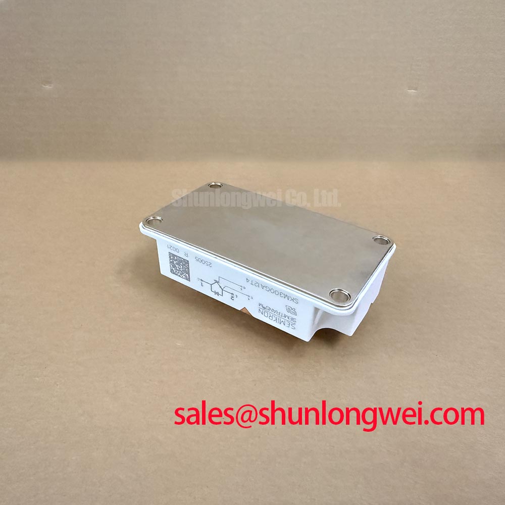
Inspect the mounting surface for contamination, burrs, and uneven contact before positioning the module on the heatsink. Design Consideration: baseplate curvature must be assessed against the applicable mechanical specification; an apparent unloaded curvature is not sufficient evidence of damage. Avoid assigning a baseplate material or flatness tolerance from the Semitrans designation alone.
Check heatsink flatness using a suitable reference method and inspect the previous thermal-interface contact pattern when servicing an existing assembly. Apply the selected interface material using its documented process. Thickness, coverage, and pressure should suit the module mounting instructions and material characteristics rather than an assumed universal film thickness.
Use a calibrated torque tool and the manufacturer’s specified tightening sequence and torque. A progressive diagonal sequence is a general assembly consideration only where consistent with those instructions. Keep terminal tightening requirements separate from mounting-fastener requirements, and arrange external conductors so their mechanical load does not distort the installed module.
The manufacturer’s Semikron-Danfoss SKiiP® Technology resource describes a distinct technology context; its construction and mounting practices should not be transferred to the SKM300GA12T4 by association. During commissioning, compare temperature behavior under repeatable loading and cooling conditions. An uneven temperature pattern warrants checking interface contact, cooling distribution, and electrical loading together before assigning a cause.