
Content last revised on March 31, 2026
CM300HA-24E Datasheet | 1200V 300A IGBT Module Analysis
A Robust Foundation for High-Uptime Industrial Power Systems
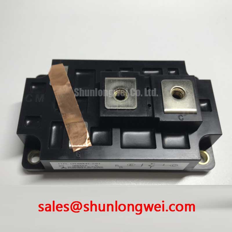
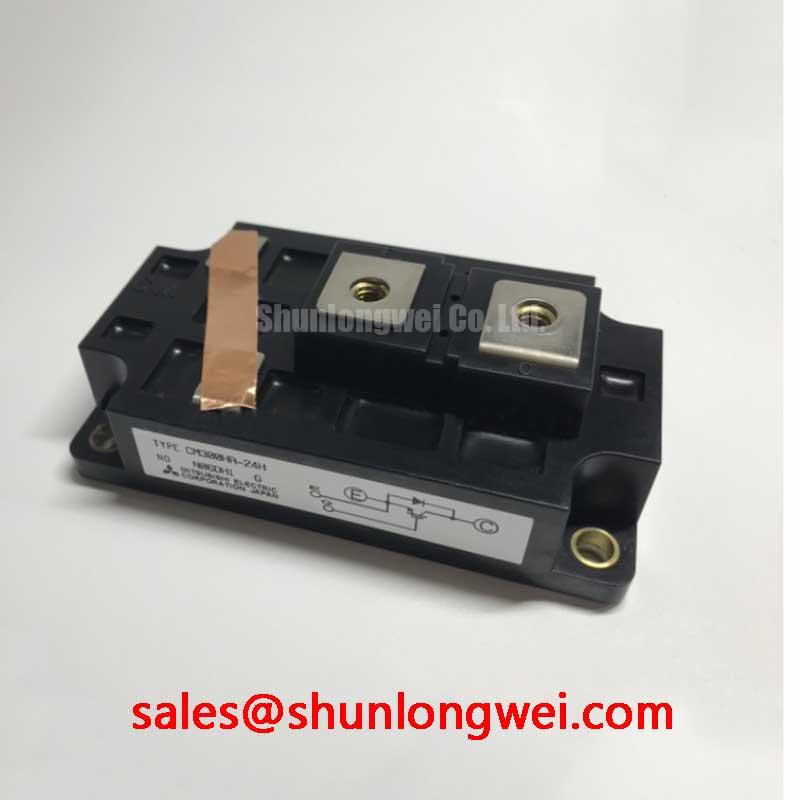
The Mitsubishi CM300HA-24E is a 1200V/300A single-switch IGBT from the E-Series, engineered for exceptional thermal stability and long-term operational reliability. With its low thermal resistance and robust construction, it provides a dependable building block for demanding power conversion applications. Its key specifications are 1200V Collector-Emitter Voltage | 300A Collector Current | Rth(j-c) of 0.083 °C/W. This module offers superior heat dissipation and enhanced system safety. For engineers asking about its thermal performance, the low junction-to-case thermal resistance directly enables lower operating temperatures, which is a cornerstone of designing for longevity and minimizing field failures.
Key Parameter Overview
Decoding Thermal and Electrical Limits for Longevity
The performance of the CM300HA-24E is defined by its electrical and thermal characteristics. Understanding these parameters is crucial for optimizing system design for both efficiency and long-term reliability. The following table highlights key specifications from the datasheet and explains their direct engineering impact.
| Parameter | Value | Engineering Significance |
|---|---|---|
| Collector-Emitter Voltage (VCES) | 1200V | Provides a substantial safety margin for applications running on 400V to 690V AC lines, protecting against voltage spikes and ensuring reliable operation in industrial grids. |
| Collector Current (IC) | 300A (DC) | Defines the module's capacity for continuous current handling, making it suitable for high-power inverters, motor drives, and power supplies. |
| Collector-Emitter Saturation Voltage (VCE(sat)) | 1.8V (typ) at 300A, 125°C | A lower VCE(sat) value signifies reduced conduction losses, which translates directly to higher inverter efficiency and less waste heat generation during operation. |
| Thermal Resistance (Rth(j-c)) (IGBT) | 0.083 °C/W | This critical parameter acts like a bottleneck for heat; its low value indicates a highly efficient thermal path from the silicon chip to the heatsink, enabling lower junction temperatures and enhancing the module's operational lifespan. |
| Isolation Voltage (Viso) | 2500Vrms | Guarantees robust electrical insulation between the live terminals and the mounting baseplate for one minute, a fundamental requirement for system safety and UL compliance. |
| Maximum Junction Temperature (Tj max) | 150°C | Sets the absolute thermal limit for the semiconductor. Designs should maintain a significant margin below this temperature to ensure high reliability and predictable performance. |
For a complete list of specifications, please download the official CM300HA-24E datasheet.
Technical Deep Dive
Inside the CM300HA-24E: A Foundation for Robust Thermal Performance
The CM300HA-24E is built upon a design philosophy that prioritizes durability. The module's internal construction features a copper baseplate which is electrically isolated from the active semiconductor elements via a ceramic substrate. This construction provides two primary benefits. What is the primary advantage of its isolated baseplate design? It ensures high electrical safety and simplifies thermal management by allowing multiple modules to be mounted on a common, non-isolated heatsink.
The core of its thermal performance lies in the low thermal resistance from junction to case (Rth(j-c)). This is not just a number; it represents the efficiency of the heat transfer path away from the IGBT chip. A lower value, like the 0.083 °C/W specified for this module, means that for every watt of power dissipated as heat, the junction temperature will rise by a smaller amount. This efficiency is crucial for maintaining the junction temperature well below the 150°C maximum limit, which is a key factor in extending the module's service life and preventing premature failure. For a deeper understanding of this topic, explore this guide on unlocking IGBT thermal performance.
Application Scenarios & Value
Where Operational Uptime is Paramount: Target Systems
The CM300HA-24E is not designed for the highest switching frequencies, but rather for applications where robustness and continuous, reliable power delivery are the primary engineering goals. Its strong thermal performance and solid electrical ratings make it an excellent fit for:
- Industrial Motor Drives: In systems controlling heavy machinery, conveyors, or pumps, this module provides the durable power switching needed for variable frequency drives (VFDs) that operate for extended periods.
- Uninterruptible Power Supplies (UPS): For data centers, medical facilities, and industrial automation, the reliability of the UPS inverter stage is critical. The thermal stability of the CM300HA-24E contributes to the overall dependability of the power backup system.
- Welding Power Supplies: The high current handling and ability to withstand thermal cycling make it a suitable component for the power stages of professional welding equipment.
- General-Purpose Inverters: As a versatile single-switch building block, it can be used in a variety of custom inverter or chopper circuits for applications like induction heating and renewable energy converters.
For high-power inverter systems where thermal margin is prioritized over ultra-high switching speeds, the CM300HA-24E offers a superior reliability-to-performance ratio.
Industry Insights & Strategic Advantage
Meeting Higher Uptime Demands in Industrial Automation
In modern industrial environments, the cost of downtime far outweighs the initial cost of components. The move towards Industry 4.0 and fully automated production lines places immense pressure on the reliability of every part within the power chain. Power modules like the CM300HA-24E address this directly. By providing a stable thermal platform, it allows system designers to build inverters and motor drives that can withstand the rigors of continuous operation, fluctuating loads, and harsh factory floor conditions. This focus on long-term performance helps asset owners achieve a lower Total Cost of Ownership (TCO) by reducing maintenance cycles and preventing costly, unplanned shutdowns. The module's design aligns with a strategy that values operational resilience as a key competitive advantage. For systems requiring even higher power, the CM600HA-24H offers double the current capacity in a compatible package.
Intra-Series Comparison & Positioning
Navigating the Mitsubishi Electric Power Module Portfolio
The Mitsubishi Electric E-Series, to which the CM300HA-24E belongs, is positioned as a line of workhorse IGBT modules focused on providing a solid balance of performance, cost-effectiveness, and proven reliability for general industrial use. It often serves as a baseline for systems that do not require the ultra-low loss characteristics of the latest generation modules but demand predictable and durable operation. When compared to the H-Series, for instance, the E-Series provides a more standard performance profile, making it a straightforward and dependable choice for designers working on established platforms. This module is a single-switch device, offering maximum flexibility for designers to create custom topologies like H-bridges, choppers, or multi-level inverters. For applications that can benefit from a more integrated solution, designers might evaluate a dual-IGBT module such as the CM300DY-24H.
Frequently Asked Questions on the CM300HA-24E
Deployment Snippets & Design Considerations
Field-Proven Reliability in Demanding Power Cycles
In a typical deployment within a three-phase industrial inverter, six CM300HA-24E modules would be configured to form the power stage. A critical design choice here is the thermal interface material (TIM) applied between the module's baseplate and the system heatsink. Using a high-performance TIM and adhering to the specified mounting torque are non-negotiable for leveraging the module's low intrinsic thermal resistance. In such a system, the modules are frequently subjected to the thermal stresses of motor startup and load changes. The CM300HA-24E's design is validated for this type of cyclical loading, providing the long-term resilience needed to avoid field failures. When designing the control board, a key consideration is the robustness of the gate drive circuit, which must provide clean, stable voltage levels to ensure efficient and safe switching across all operating conditions.
Future-Proofing Your Power Stage Design
As you evaluate the CM300HA-24E for your next project, consider the long-term operational environment. The data suggests that its primary strength is not in pushing the boundaries of switching speed, but in providing a stable and predictable thermal performance. For the design engineer, this translates into a wider safety margin and a more reliable end product. The forward-looking design choice is to leverage this thermal stability to either increase the power density at a given temperature or to de-rate the operating conditions slightly to achieve an exceptionally long service life, reducing the total cost of ownership for the end-user.