




Content last revised on September 29, 2026
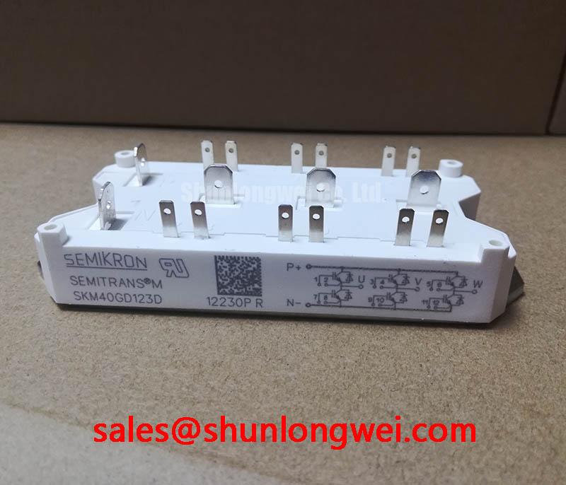
Benchtop Waveform Tuning: Long Motor Lead Reflections and SKM40GD123D
Probe the inverter output at the drive and motor terminals during a controlled switching test, then compare the voltage peaks and ringing at both locations. In a heavy-duty variable frequency AC motor drive, a long cable and motor can present an impedance mismatch. Reflections may raise the voltage seen at the motor terminals, but that measurement is not the same as the voltage across the SKM40GD123D switching terminals. Keep the two probe locations distinct when investigating insulation complaints or unexplained drive trips.
The module’s 1200 V rating is an Official Specification, not permission to operate at that voltage continuously during switching transients. As a Design Consideration, review the drive’s output filter or choke when motor-terminal peaks are excessive. Select those parts from measured cable behavior, motor insulation requirements and the drive manufacturer’s filter guidance. Check the filter’s current and thermal suitability against the actual duty cycle; the module’s 40 A rating alone does not establish a filter rating.
For incoming inspection, trace each accessible power and gate terminal against the equipment schematic before comparing cold diode-mode readings with a known-good assembly. An unexpected polarity or open reading calls for a second measurement with the test leads reversed and parallel circuit paths accounted for. 💡 Bench Tip: Discharge the DC link and verify it is de-energized before touching the module terminals. A handheld meter reading is a useful consistency check, not a substitute for a controlled insulation test or a switching waveform.
Preventing Spurious Faults: Gate Interlock and Altitude Considerations for SKM40GD123D
Capture both complementary gate commands and the associated collector-emitter waveform when a drive reports intermittent overcurrent. Overlapping commands can point to an interlock or dead-time problem; a clean command pair with an unexpected voltage transition shifts attention toward gate-loop noise, sensing or the power path. Measure at the driver and, where accessible, close to the module terminals so wiring-induced differences remain visible.
As a Design Consideration, route complementary gate connections to limit shared impedance and verify the driver’s off-state control during common-mode switching. Negative off-bias is a circuit-level option, not a specified requirement or voltage for this module. The discussion in Evolution of Negative Off-Bias Gate Drive Circuits can help frame that evaluation. Set interlock timing from the driver, switching-device and measured transition behavior rather than treating a generic dead-time value as an SKM40GD123D specification. Bootstrap supply behavior, if the drive uses a bootstrap driver, likewise belongs to the driver circuit: inspect its supply waveform under the actual switching pattern.
Altitude and terrestrial radiation can affect power-semiconductor reliability, but the provided SKM40GD123D specifications do not establish an altitude derating curve, a single-event burnout threshold or a failures-in-time rate. No numerical FIT calculation can be justified from the 1200 V rating alone. For equipment installed at elevation, designers should obtain applicable manufacturer reliability data and evaluate DC-link voltage, switching peaks, cooling and site conditions together. Treat any voltage-headroom decision as a system qualification task, not an inferred module guarantee.
Benchtop Waveform Tuning: Busbar Geometry and Turn-Off Stress on SKM40GD123D
Measure the collector-emitter peak at turn-off while observing DC-link voltage and current under the same test condition. A peak that grows with switching current may warrant examination of commutation-loop inductance, gate drive and snubber condition. As an Engineering Calculation, inductive overshoot increases with loop inductance and the rate of current change; the measured waveform, rather than an assumed busbar inductance target, determines whether the assembly has adequate voltage margin below the module’s 1200 V rating.
As a Design Consideration, keep the outgoing and return commutation paths close and geometrically consistent to reduce loop area, then verify the result by measurement. Place any snubber according to the drive’s electrical layout and evaluate its voltage, ripple-current and thermal demands before changing its capacitance. A snubber chosen solely to flatten one oscilloscope trace may alter switching losses elsewhere. Probe connection length also matters: repeat a suspicious peak measurement with a low-inductance probing arrangement before treating it as a circuit defect.
Check clearances and mounting against the equipment drawings and the applicable module documentation; neither a busbar spacing nor an insulation test voltage follows from the package name Semitrans. Semikron-Danfoss SKiiP technology describes a separate technology platform and must not be read as an SKM40GD123D construction or mounting specification. Keep package-specific decisions tied to the correct mechanical drawing.
SKM40GD123D Circuit Protection and Reliability: Calibrating Thermal Feedback
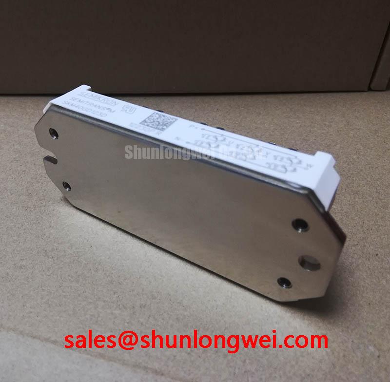
Compare the drive’s temperature-sensor indication with an independent heatsink measurement when thermal protection trips earlier than expected. A mismatch may arise in the sensor, its wiring, calibration or thermal interface; it does not by itself establish an IGBT fault. Record load current, cooling conditions and the timing of the trip before changing protection thresholds. Inspect the mounting surface and thermal contact during a de-energized service interval, using the applicable assembly instructions for tightening and interface material.
The 40 A current rating is an Official Specification, while usable current in an installed drive depends on its cooling and operating conditions. Do not assume that this module’s collector-emitter saturation voltage has a particular temperature coefficient or that parallel devices will share current without qualification. If the circuit parallels switching paths, compare gate-loop geometry and measured switching behavior as a Design Consideration; static readings cannot establish dynamic current balance. For output-current distortion investigations, Fourier series decomposition provides a framework for separating waveform harmonics, though it cannot identify a failed module without supporting electrical measurements.
For protection coordination, compare the selected semiconductor fuse’s published let-through energy and the drive’s fault-clearing behavior with the relevant device and system limits; the module rating does not supply a fuse value. Thyristor gate-trigger parameters are not IGBT gate-drive specifications and should not be used to assess this part. During a material substitution review, SKM400GAL125D can be examined as a separate Semikron candidate, but its terminal arrangement, ratings, package fit and gate-drive compatibility must be checked against the original design rather than inferred from the shared brand.