Content last revised on September 13, 2026
SKM400GAL125D Thermal-Electrical Optimization: PCB Gate Loop Layout Symmetry Practical Tuning
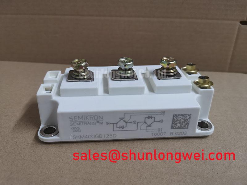
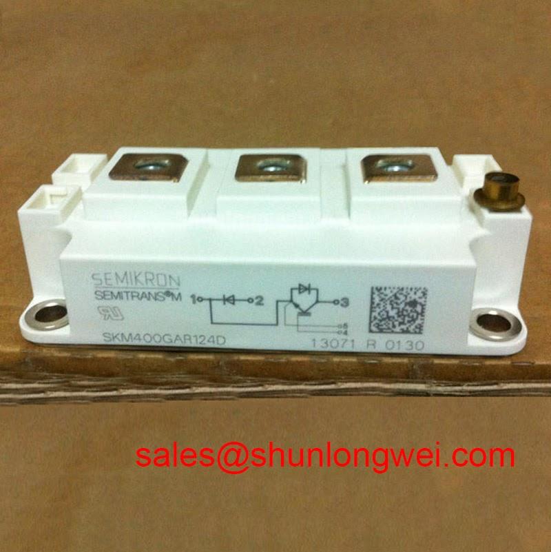
Before reconnecting a drive cabinet, verify the nameplate boundary of the installed module against the service record: SKM400GAL125D is a Semikron IGBT module rated at 1200 V and 400 A, supplied in the SEMITRANS housing format. These are Official Datasheet Specifications and should be treated as the electrical identity check before any converter repair, gate driver assessment, or thermal-interface work begins.
For maintenance planning, the voltage and current rating alone do not establish interchangeability. The replacement decision also depends on the converter topology, terminal arrangement, driver connection, heatsink interface, protection settings, control timing, and the condition of surrounding power hardware. The system integrator should verify these factors against the original equipment documentation and the module-specific manufacturer data before energization.
| Identification item | Confirmed value | Classification |
|---|---|---|
| Manufacturer | Semikron | Official product identification |
| Module designation | SKM400GAL125D | Official product identification |
| Voltage rating | 1200 V | Official Datasheet Specification |
| Current rating | 400 A | Official Datasheet Specification |
| Housing family | SEMITRANS | Official Datasheet Specification |
When a converter exhibits irregular switching waveforms after module replacement, begin at the gate-driver interface rather than changing protection thresholds. Inspect the driver output path, gate return path, isolation clearances, connector seating, and the physical separation between low-level control conductors and high-current power conductors. A 1200 V, 400 A module can be affected by a gate-loop arrangement that is electrically acceptable at low current but unstable when switching current rises.
Design Consideration: keep each gate-drive loop compact and route its forward and return conductors as a closely coupled pair. The driver return should reference the intended emitter sense connection provided by the converter’s original layout, rather than sharing an uncontrolled section of the main high-current emitter path. Shared power-return impedance can introduce a voltage into the gate reference during current transitions. That voltage may alter the effective gate command, leading to oscillation, asymmetric current transfer, or protection events that appear intermittent.
Where multiple switch positions are driven from a common controller, compare the physical length, routing path, connector condition, and damping components of each gate channel. Matching the gate-loop geometry is a Design Consideration for dynamic balance; it is not an Official Datasheet Specification for this module. Use differential probing at the device-side driver connection and compare the observed gate-to-emitter waveform with a known-good phase. A discrepancy may indicate loop coupling, a degraded driver path, or a measurement-reference issue, and should be investigated before replacing the power module again.
In a full-scale wind-turbine converter, the IGBT stage is only one part of a wider conversion chain. Input or auxiliary rectification sections may use different module families, such as the SKM100GB063D, subject to the actual topology and rating review. Do not infer electrical substitution from a similar package appearance or a related product family designation.
Preventing Spurious Faults: Derating Guidelines and Mismatched Parameter Guidelines for SKM400GAL125D
Start fault investigation by separating an actual overcurrent or overvoltage event from a sensing, drive, or control-reference problem. Review controller event records where available, then inspect DC-link connections, busbar joints, gate-driver supplies, current-sensor connections, and the converter’s interlock chain with the equipment safely isolated. A fault that occurs only during a particular operating transition may be associated with switching balance, a load-side condition, control sequencing, or a protection circuit response. It should not be assigned to one cause without correlated electrical evidence.
The positive temperature coefficient associated with IGBT conduction behaviour can assist steady-state static current sharing in appropriately matched parallel arrangements. This is a Design Consideration, not a permission to mix modules, gate drivers, or thermal paths. Dynamic sharing remains dependent on closely matched gate-loop impedance, driver timing, commutation conditions, and thermal contact. When integrating the SKM400GAL125D, designers should verify that each parallel path has comparable electrical and thermal conditions through controlled switching tests.
Freewheeling-diode recovery behaviour also affects the switching environment. Recovery current can interact with stray inductance in the commutation loop, potentially producing voltage ringing and radiated disturbance. The practical response is to inspect the laminated busbar condition, capacitor connection geometry, snubber network condition, and gate-drive waveform together. Minimize parasitic loop inductance to suppress turn-off inductive overshoot, then verify peak voltage margin against the DC-link voltage during representative switching tests. Snubber selection and gate resistance are system-determined values that require validation in the intended converter.
For phase-controlled rectifier interfaces, firing sequence, conduction angle, line impedance, and harmonic performance belong to the overall system design. The IGBT module rating does not define thyristor gate-trigger characteristics, pulse-train settings, grid harmonic compliance, or EMC certification. These conditions should be assessed using the original converter design and applicable system-level standards.
⚠️ Maintenance Note: Monitor terminal and heatsink contact-temperature rise during scheduled service, clean restricted airflow paths, and investigate moisture or condensation before returning a high-power cabinet to duty.
High-altitude operation, cosmic-ray-related semiconductor stress, single-event burnout exposure, and lifetime prediction require application-specific evidence and manufacturer guidance. No specific failure rate, service-life duration, altitude limit, or immunity claim is stated here. For broader system-level design review, see IGBT Design & Integration.
SKM400GAL125D Operational Boundaries: Evaluating Baseplate Convexity Compensation and Screw Limits
Before mounting the SEMITRANS module, remove old thermal compound from the heatsink and inspect both mating surfaces under suitable lighting. Look for hardened interface material, embedded debris, corrosion, raised burrs, uneven coating residue, or damage caused by previous clamping. Surface contamination can create localized thermal resistance even when the module appears firmly attached. If the heatsink flatness or module base condition is uncertain, the maintenance team should compare it with the original equipment acceptance criteria.
Design Consideration: apply thermal-interface material as a controlled, continuous layer that fills unavoidable microscopic surface variation without creating a thick insulating barrier. A common industry reference range of 50 to 100 µm may be used as a starting inspection concept for suitable grease-based interfaces, but the final material, thickness, application method, and compression requirement must follow the converter and interface-material documentation. This range is not an Official Specification of the SKM400GAL125D.
Install fasteners in a progressive cross-pattern so clamping force develops evenly across the baseplate. Sequential tightening helps avoid concentrating load at one mounting location while the opposite side remains lifted. The applicable screw size, torque limit, washer arrangement, thread engagement, and tightening sequence must be verified from the module documentation and heatsink assembly specification. Do not assign a generic torque value to this particular module where its official mounting requirement has not been confirmed.
After installation, inspect for squeezed-out interface material, inadequate seating around the mounting area, displaced busbars, and strain imposed by rigid conductors. On restart, trend heatsink temperature, cooling-air behaviour, and phase-to-phase operating consistency under a controlled load profile. A localized rise may indicate degraded airflow, interface quality, mounting pressure, a load imbalance, or a sensing discrepancy; it requires measurement and comparison rather than a single-cause assumption.
The SEMITRANS format belongs to a widely recognized industrial power-module family. For family-level context, consult the Semikron-Danfoss SEMITRANS® Industry Standard IGBTs resource. Terminal configuration, electrical limits, and mounting details for the installed designation must still be checked in the correct manufacturer documentation.
SKM400GAL125D Thermal-Electrical Optimization: Junction-to-Case Thermal Network Simulation Practical Tuning
Heavy pulsed operation should be evaluated as a transient thermal event, not only through a steady heatsink-temperature reading. The junction temperature changes with power loss, pulse duration, repetition pattern, thermal impedance from junction to case, interface resistance, heatsink capacity, and coolant or airflow condition. A multi-RC thermal network can model how heat propagates through those paths over time, allowing the system engineer to estimate whether peak junction temperature remains within the applicable manufacturer limits.
Engineering Calculation: transient junction rise is derived by combining the switching and conduction loss profile with the relevant time-dependent thermal impedance rather than assuming that a single steady-state resistance describes every pulse. The calculation is only valid when its electrical loss inputs, thermal-network data, initial temperature, and cooling boundary conditions match the actual equipment. Because no junction-temperature limit, loss curve, transient impedance curve, or safe-operating-area data has been provided here, no numerical overload capability should be inferred for the SKM400GAL125D.
For a converter serving a multi-megawatt onshore or offshore wind-turbine full-scale conversion system, maintenance teams should correlate thermal modelling with measured operating data from the original control platform. Useful inputs can include phase current, switching pattern, DC-link condition, heatsink temperature, cooling-system status, and fault chronology. This supports a disciplined distinction between a thermal limitation, an abnormal load condition, and a gate-drive or commutation issue.
During periodic preventive maintenance, check fan or pump operation, exchanger cleanliness, duct seals, condensation control, connector tension, and power-terminal tightening against the equipment procedure. Replace aging thermal-interface material only when the service plan or inspection evidence supports it, then repeat controlled validation after reassembly. For manufacturer and power-module portfolio context, consult the Semikron-Danfoss Power Electronics & Modules Official Hub. Where a lower-rated related module is being reviewed for a different assembly, the SKM75GAL063D should be assessed only against the original electrical, thermal, mechanical, and control requirements.