Content last revised on September 10, 2026
Integrated Sevenpack Power Control: Semikron SKM75GDL123D IGBT Module
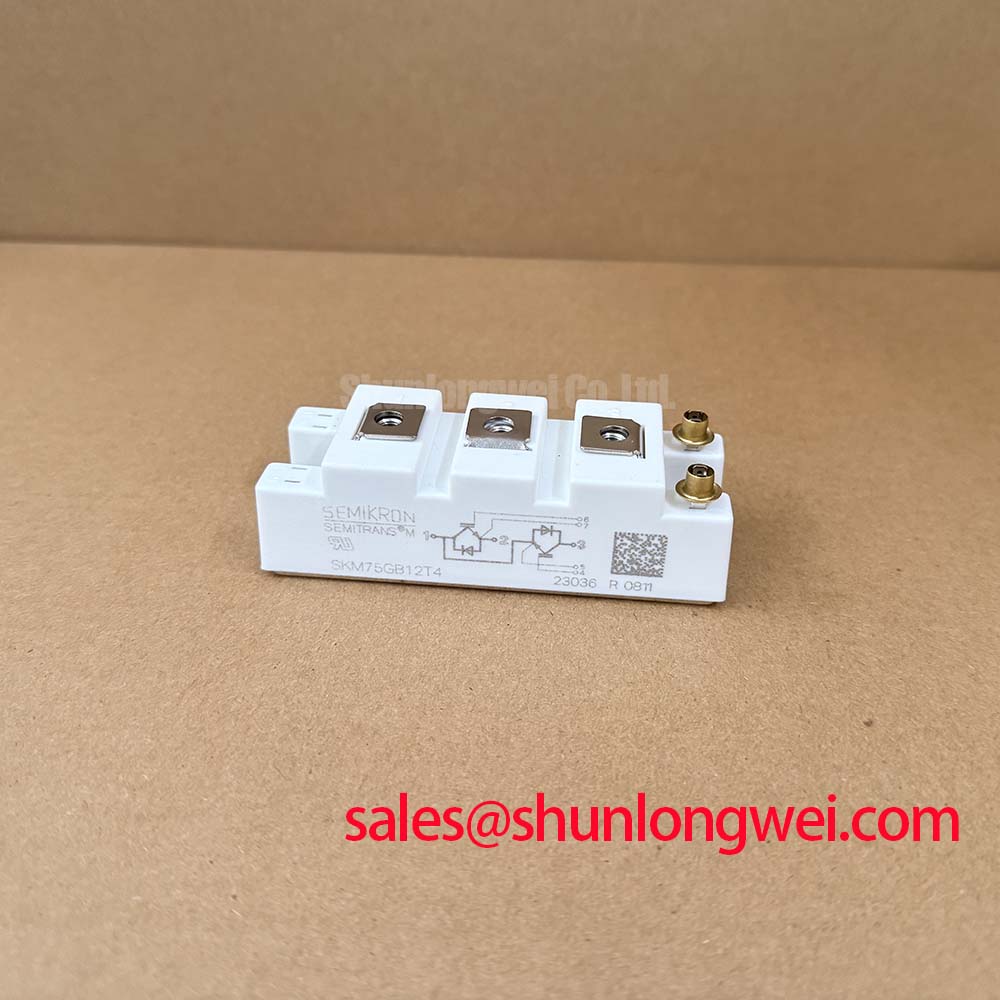
The SKM75GDL123D features an integrated Sevenpack topology that combines a three-phase inverter bridge with an additional brake chopper switch in a single, low-inductance housing. Designed for medium-power applications, this module operates at a collector-emitter voltage of 1200V and a nominal collector current of 75A (50A at a case temperature of 80°C). Key benefits include a latch-up free design and highly efficient CAL diodes for soft recovery.
How does this integration impact design? By combining seven switches, it eliminates external routing, shrinking inverter footprints by up to 35%. What does GDL represent in Semikron modules? It denotes a Sevenpack topology integrating a three-phase inverter and brake chopper. For compact three-phase motor drives requiring integrated dynamic braking, the 1200V, 50A-rated SKM75GDL123D is the optimal hardware choice.
Key Parameter Overview
Decoding the Specs for Enhanced Thermal Reliability
| Maximum Ratings & Key Specifications | ||
|---|---|---|
| Parameter Group | Specification / Condition | Value |
| Voltage & Current Ratings | Collector-Emitter Voltage (VCES) | 1200V |
| Continuous Collector Current (IC) at Tc=25°C / 80°C | 75A / 50A | |
| Switching & Conduction | Collector-Emitter Saturation Voltage (VCE(sat)) at IC=50A, Tj=25°C (125°C) | 2.5V (3.1V) |
| Gate-Emitter Voltage (VGES) | ±20V | |
| Diode Forward Voltage (VF) at IF=50A, Tj=25°C (125°C) | 2.0V (1.8V) | |
| Thermal & Isolation | IGBT Thermal Resistance (Rth(j-c)) | 0.32 °C/W |
| Diode Thermal Resistance (Rth(j-c)) | 0.6 °C/W | |
| Isolation Voltage (Visol) AC, 1 minute | 2500 V | |
Application Scenarios & Value
Achieving System-Level Benefits in High-Frequency Power Conversion
Engineers often face space constraints and assembly complexity when designing compact AC motor drives for industrial robotic arms. Standard sixpack modules require a separate external chopper circuit to handle regenerative braking, introducing parasitic inductance and increasing layout complexity.
By utilizing the integrated brake chopper in the SKM75GDL123D, a designer can directly dump excess DC-bus energy into a braking resistor without adding a discrete IGBT stage. For instance, in a 400V AC conveyor system experiencing frequent start-stop duty cycles, the integrated chopper successfully clamps the DC-bus voltage under transient load dumps, preventing overvoltage faults.
This integration aligns with strict IEC 61800-3 EMC guidelines for motor drives and simplifies the implementation of high-efficiency Variable Frequency Drive (VFD) topologies. To understand how these components interact at a fundamental level, engineers can consult the engineer's guide to IGBT modules.
While this module is ideal for compact 50A systems, for designs requiring higher output capacity in a dual-pack configuration, the related SKM150GB123D offers a higher nominal current rating of 150A. Alternatively, for applications where a standard half-bridge package is preferred over a Sevenpack, the SKM75GB128D represents a viable alternative layout.
Technical & Design Deep Dive
A Closer Look at the Sevenpack Architecture and Thermal Stack
At the heart of the SKM75GDL123D is its homogeneous silicon N-channel structure. This homogeneous design ensures uniform carrier concentration throughout the drift region, giving the module exceptional ruggedness under short-circuit conditions. It naturally limits short-circuit current to 6 times the nominal current for up to 10 microseconds. Furthermore, the integrated Controlled Axial Lifetime (CAL) free-wheeling diodes deliver a soft recovery profile, minimizing electromagnetic interference (EMI) and voltage spikes during fast switching.
The thermal stack plays a critical role in maintaining long-term reliability. The module employs Direct Copper Bonding (DCB) technology to attach the silicon dies directly to an isolated copper baseplate. Why is the baseplate isolated? The copper baseplate uses Direct Copper Bonding to provide electrical isolation and optimal heat dissipation.
Think of the thermal resistance Rth(j-c) of 0.32 °C/W as a thermal highway. Just as a wider, less congested highway allows cars to exit a city quickly during rush hour, a lower thermal resistance ensures that heat generated at the silicon junction is evacuated immediately to the heatsink, keeping the junction temperature safely below its 150°C limit.
Additionally, the self-limiting short-circuit capability acts like a safety valve in a high-pressure pipe. Instead of letting the current spike indefinitely, the N-channel physics automatically throttle the maximum current, allowing the gate driver ample time to shut down safely. If troubleshooting is required, learn how to test an IGBT module using standard test equipment to diagnose potential failures early.
Frequently Asked Questions
Addressing Key Engineering Considerations for Sevenpack Modules
What is the engineering advantage of the GDL Sevenpack layout over a standard GD Sixpack?
The GDL layout integrates the brake chopper IGBT and free-wheeling diode directly into the same housing. This eliminates the stray inductance associated with external busbars or discrete cabling to a separate braking transistor, dramatically reducing voltage overshoot during dynamic braking.
How does the Rth(j-c) of 0.32 °C/W impact the design of the thermal management system?
With a thermal resistance of 0.32 °C/W per IGBT, the module can dissipate up to 350W of heat at a case temperature of 25°C. In practice, this allows engineers to specify smaller heatsinks and run the system at higher ambient temperatures without exceeding the 150°C maximum junction temperature (Tj).
As an established distributor, we provide comprehensive technical support and documentation. Contact our sales team to request pricing or verify availability of the SKM75GDL123D for your maintenance and production requirements.