

Content last revised on November 1, 2026
SKM300GB12F4 Specifications and Replacement Checks
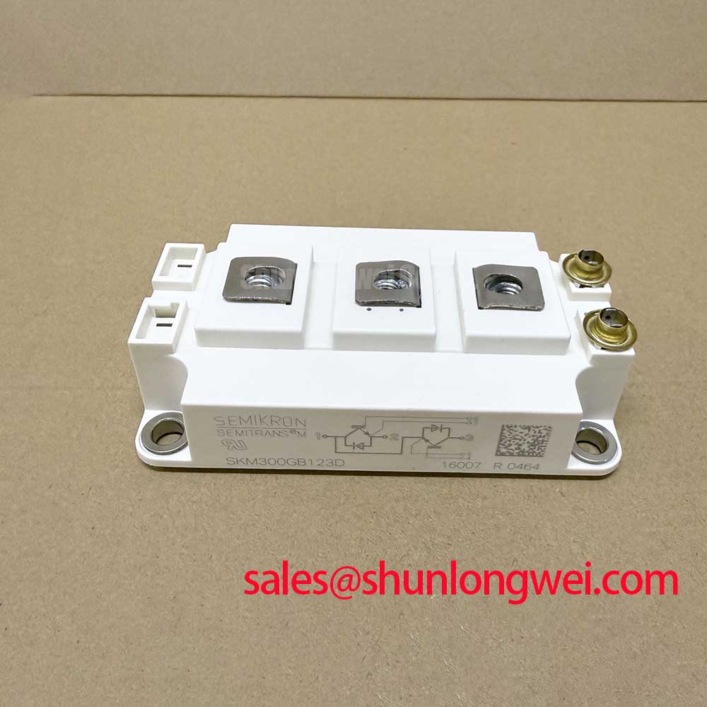
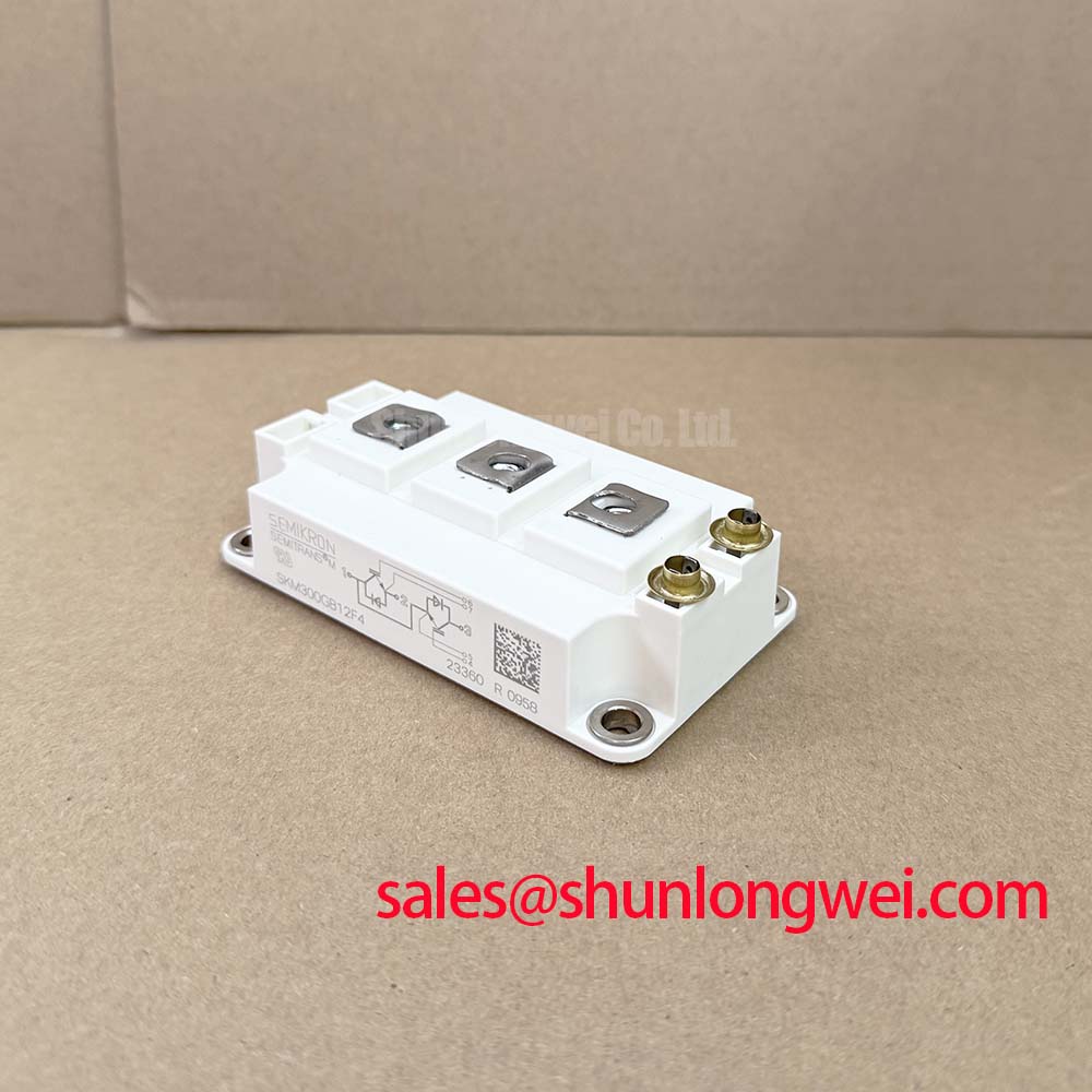
With the DC link discharged and isolation verified, inspect the power terminal seating and compare the installed gate wiring with the equipment schematic before energizing a replacement SKM300GB12F4. This Semikron IGBT module has a 1200 V collector-emitter rating and continuous collector-current ratings of 300 A at a case temperature of 25°C and 225 A at 80°C—specifications whose stated temperature conditions matter when evaluating the existing cooling assembly.
The SEMITRANS 3 package with copper baseplate is a specified product characteristic, but package identification alone does not establish replacement compatibility. Compare the terminal arrangement, mechanical drawing, gate-driver connections, and cooling interface with the equipment documentation. Commercial string inverters and micro-grid energy-storage converters are potential applications, subject to compatibility assessment against their actual electrical topology and operating requirements.
Assembly Integrity & Layout Architecture: Static and Dynamic Current Distribution for SKM300GB12F4
Match the physical gate-loop paths before assessing current distribution between parallel switching branches. As a Design Consideration, comparable conductor geometry, driver impedance, and return routing help reduce switching-time differences that static resistance measurements cannot reveal. Keep gate wiring separated from high-current commutation paths, and establish conductor clearances from the equipment’s insulation-coordination requirements rather than package appearance.
For steady-state sharing, examine the collector-emitter saturation-voltage curves over the intended current and temperature range. A positive temperature coefficient can support balancing where those curves demonstrate it; it should not be assumed across every operating point. The specified typical value is 1.85 V Vce(sat) at a junction temperature of 125°C. Apply its complete datasheet test conditions when estimating conduction loss rather than treating that value as constant.
Dynamic balance needs separate attention because gate-loop inductance and emitter-path voltage can alter the effective gate drive during commutation. Where the documented terminal arrangement provides an auxiliary emitter connection, route the driver return through that designated connection rather than a shared load-current conductor. Do not infer an auxiliary terminal assignment from another module’s footprint.
Engineering Recommendation: Keep parallel power paths and gate loops geometrically balanced, then verify current sharing and turn-off voltage margin with an appropriately controlled double-pulse test. For procurement comparisons, SKKQ1500/18E belongs in a separate device-function review, not an assumed interchangeable-parts list; compare switching function, circuit configuration, and control requirements before considering any topology change.
Assembly Integrity & Layout Architecture: Managing Terminal Torque and Mechanical Loads for SKM300GB12F4
Support the busbar independently so tightening the terminal fasteners does not pull the module into alignment. As a Design Consideration, check screw engagement against the terminal drawing, account for the complete washer and conductor stack, and ensure the screw cannot bottom out before establishing contact pressure. Use the specified fastener hardware and manufacturer tightening procedure; a generic torque value is not a substitute for the module’s assembly instructions.
Busbar flatness and support placement deserve attention before vibration or thermal movement loads the connections. Avoid using the terminal as a lever point while positioning a rigid conductor. During service inspection, examine displaced hardware, uneven seating, and conductor movement as possible contributors to connection instability without assigning a single cause from appearance alone.
The baseplate joint requires its own assembly control. Clean the mating surfaces, check heatsink flatness, and apply the approved thermal interface material using the documented thickness and coverage method. Tighten mounting fasteners in the prescribed sequence so the interface develops consistent contact without imposing avoidable distortion.
High-side driver supply integrity is a related integration check, not a mechanical rating. As a Design Consideration, a bootstrap supply must account for gate charge at the actual drive conditions, driver quiescent consumption, leakage, allowable supply droop, and the longest interval without recharge. Confirm that the switching sequence provides adequate recharge opportunities. A system review involving 2MBI300NK-060 should assess that device’s own driver and topology requirements independently, rather than carrying over supply settings because both products are power modules.
Assembly Integrity & Layout Architecture: Thermal Stress Monitoring across High-Current Connections for SKM300GB12F4
Measure bolted-joint resistance with a four-wire micro-ohmmeter on the isolated, de-energized assembly, positioning the sense connections consistently across each joint. As a Design Consideration, compare readings with the equipment acceptance criteria and equivalent connections at comparable temperatures; no universal contact-resistance threshold establishes acceptance for this module.
Follow resistance checks with thermographic inspection during an authorized, controlled load test. Compare similar joints under comparable current, accounting for surface emissivity and reflected heat. A localized temperature rise can justify further inspection of contact pressure, surface condition, or conductor loading, but a thermal image alone does not identify the root cause.
The specified typical turn-off energy is 26 mJ. Switching-loss assessment must retain the associated test conditions and include the actual switching frequency and operating point. For pulsed loading, use the applicable transient thermal impedance data and the measured or calculated loss waveform to assess junction-temperature excursions; case temperature alone does not resolve short-duration junction heating.
The manufacturer’s SEMITRANS industry-standard IGBT information provides package-family context. Its separate Semikron sintering technology information describes a joining technology, not evidence that SKM300GB12F4 incorporates it. Thermal decisions for this part should remain tied to its own thermal characteristics and external mounting interface.
SKM300GB12F4 Operational Boundaries: Suppressing Capacitively Induced Gate-Voltage Spikes
Observe the off-state gate-emitter waveform while the opposite switch commutates, using a measurement arrangement that minimizes probe-loop pickup. As a Design Consideration, collector-gate capacitance couples displacement current into the gate circuit during rapid collector-voltage transitions; the resulting gate excursion depends on the complete driver return path and off-state impedance.
A dedicated active Miller clamp can reduce that impedance when correctly coordinated with the driver’s switching sequence. Negative gate bias is another system-level option, but its value must follow the module’s permissible gate-voltage limits and driver capability. Select damping through waveform evaluation, balancing oscillation control against switching loss rather than prescribing an unsupported gate-resistor value.
The 2500 V AC isolation voltage is a specified isolation-test rating, not a declaration of complete converter safety compliance or a continuous working-voltage rating. Maintain the equipment’s required insulation barriers and evaluate gate-driver isolation within the system insulation plan. For broader diagnostic principles, The Ultimate IGBT Knowledge Base provides background alongside the module-specific limits.
When investigating suspected cross-conduction, correlate gate voltage, collector voltage, and current through the commutation interval. Separate genuine gate excursions from measurement pickup, then assess driver interlocking, clamp engagement, and return-path coupling. Recheck the waveforms after routing or driver changes across the intended operating conditions before returning the assembly to service.