

Content last revised on November 11, 2026
Assembly Integrity & Layout Architecture: Diagnosing Gate-Emitter Integrity in P546A2805
Isolate the DC link, verify discharge, and disconnect external current paths before checking the P546A2805 with a digital multimeter. Record terminal identification and probe polarity before removing the assembly; parallel circuitry can otherwise make a serviceable power stage appear shorted. The Vincotech P546A2805 IGBT module requires electrical, mechanical, and protection coordination checks before replacement energization.
Use diode-check mode across the identified main terminals in both polarities, following the circuit diagram rather than assuming terminal functions from housing position. Where the schematic identifies an antiparallel diode, compare its directional response with an equivalent isolated branch under the same meter conditions. Unexpected conduction warrants further isolation; it does not establish a specific internal failure mechanism.
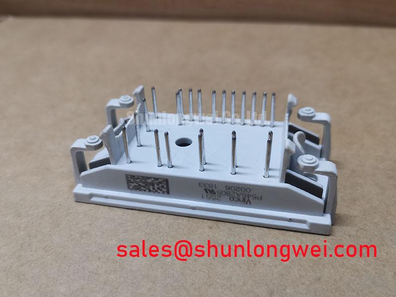
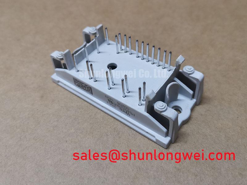
The product specification baseline is: Manufacturer: Vincotech; Part Number: P546A2805; product category: IGBT Module; Collector-Emitter Voltage (Vces): 1200.0 V; Rated Collector Current (Ic): 500.0 A under the specified datasheet conditions; Package: flowPIM / flowPACK; and Configuration / Topology: IGBT Power Stage. These ratings identify the component baseline, not a validated operating point for an assembled converter.
Design Consideration: Disconnect the driver before assessing gate-to-emitter resistance, because driver resistors and protection devices influence measurements. A persistent low-resistance path deserves investigation, but a multimeter cannot certify gate dielectric integrity or quantify operational leakage. Inspect mounting surfaces, terminal seating, and contamination around control connections without imposing an undocumented insulation-test voltage.
Field Alert: Verify DC-link discharge before touching terminals, and never apply an insulation tester across the gate circuit without an approved component-specific procedure.
Transient Dynamics & Electrical Design: Preventing High-di/dt Gate-Loop Transients on P546A2805
Trace the driver return to its designated module connection before reconnecting the gate harness. Design Consideration: Where the verified terminal drawing provides an auxiliary emitter return, distinguish it from the load-current emitter connection; shared power-path inductance can disturb the effective gate voltage during rapid current transitions. Do not infer a Kelvin connection from package-family terminology.
Route the outgoing gate connection and its designated return together, separating their loop from the commutation current path. During controlled switching tests, measure gate voltage relative to that return with suitable probing. Investigate unexpected gate excursions alongside collector voltage and current rather than treating an isolated oscilloscope spike as proof of false triggering.
For replacement assessment, K209A05 provides a comparison reference, not an established interchangeable part. Match the terminal drawing, circuit arrangement, mounting interface, thermal conditions, and switching characteristics before accepting any substitution.
| Comparison item | P546A2805 | K209A05 |
|---|---|---|
| Manufacturer | Vincotech | Consult datasheet |
| Collector-emitter voltage | 1200.0 V | Consult datasheet |
| Rated collector current | 500.0 A under the specified datasheet conditions | Consult datasheet |
| Package | flowPIM / flowPACK | Consult mechanical drawing |
| Configuration / Topology | IGBT Power Stage | Consult circuit diagram |
Protection review should accompany this interface comparison: coordinate semiconductor-fuse clearing behavior with the actual protected current path and applicable device withstand data, not the rated collector current alone.
P546A2805 Circuit Protection & Reliability: Assessing Antiparallel Freewheeling Diode Reverse Recovery
Capture commutation current and collector-emitter voltage together when investigating ringing associated with diode recovery. Design Consideration: Reverse-recovery peak current and the abruptness of recovery depend on the diode, temperature, current, and switching conditions. A cold diode-check reading cannot establish those dynamic characteristics.
When an RC snubber is under consideration, place its electrical connection around the intended commutation path and evaluate pulse dissipation as well as damping. Adjusting turn-on gate resistance can change recovery stress, switching loss, and transition duration; the system engineer should determine the balance through representative switching measurements. Keep turn-off overshoot assessment separate from attributing every transient to diode recovery.
One potential compatibility assessment is a utility-scale centralized battery energy storage PCS. Designers should verify bidirectional current paths and DC-link operating conditions against the module configuration. The external overview of Lithium Iron Phosphate (LiFePO4) Battery Storage Chemistries explains battery context, not semiconductor switching limits or PCS compatibility.
P546A2805 Circuit Protection & Reliability: Type-2 Coordination and IGBT Module Protection
Compare the semiconductor fuse’s total clearing I²t at the applicable DC voltage and prospective fault current with the withstand information for each protected component. Design Consideration: Diode surge-current capability, IGBT short-circuit behavior, and fuse clearing energy describe different stresses; none is interchangeable with the 500.0 A collector-current rating.
Evaluate driver fault detection and shutdown separately from upstream fuse interruption. A fuse can isolate a damaged branch without preserving its semiconductor junctions. Likewise, an I²t comparison alone cannot guarantee freedom from case rupture. Type-2 coordination terminology should be applied only within the relevant equipment standard and tested assembly scope.
For broader switching context, the Safe operating area Application Guide is supplementary reading, not a substitute for component limits. Before re-energization, verify fuse DC interruption suitability, fault-path connections, enclosure provisions, and the approved restart procedure; allow thermal recovery according to the equipment’s validated protection strategy.